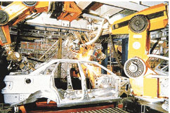
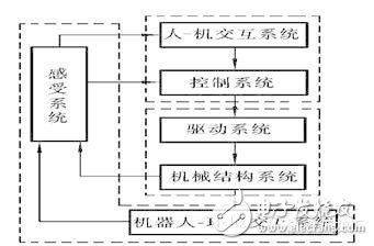
Industrial robot is a multi-functional, multi-degree-of-freedom mechatronics automatic mechanical equipment and system that can complete certain operational tasks in the manufacturing process through repeated programming and automatic control. It can be combined with a manufacturing host or a production line to form a single or multiple machines. Machine automation system, in the unattended, to achieve a variety of production operations such as handling, welding, assembly and spraying. Robotics Science Popularization First, industrial robots are divided into four types according to the movement of the arm: 1. The right-angled coordinate arm can move along three orthogonal coordinates; 2. The cylindrical coordinate type arm can be used for lifting, turning and telescopic movement; 3. The spherical coordinate type of the arm can be rotated, pitched and telescoped; 4. The articulated arm has multiple rotating joints. Second, the control function of the industrial robot according to the movement of the actuator can be divided into points and continuous track type. 1. The point type only controls the accurate positioning of the actuator from one point to another, and is suitable for machine loading and unloading, spot welding and general handling, loading and unloading operations; 2, continuous track type can control the actuator to move according to a given trajectory, suitable for continuous welding and painting operations. Third, the industrial robot is divided into two types: programming input type and teaching input type according to the program input mode: 1. The programming input type is to transfer the programmed program files on the computer to the robot control cabinet through RS232 serial port or Ethernet communication. 2. There are two teaching methods for teaching input type: One is that the operator uses a manual controller (teaching operation box) to transmit the command signal to the drive system, so that the actuator can be operated in accordance with the required sequence of motions and motion trajectories; The other is that the operator directly leads the actuator and performs it in the required sequence of actions and motion trajectories. At the same time of the teaching process, the information of the working program is automatically stored in the program memory. When the robot automatically works, the control system detects the corresponding information from the program memory, and transmits the command signal to the driving mechanism, so that the executing mechanism reproduces the teaching. Various actions. The industrial robot that teaches the input program is called a teaching and reproducing industrial robot. Fourth, intelligent industrial robot Industrial robots with tactile, force or simple vision can work in more complex environments; if they have recognition functions or further increase adaptive, self-learning functions, they become intelligent industrial robots. It can adapt to the environment according to the "macro" selection or self-programming given by people, and automatically complete more complicated work. [Other knowledge] First, the characteristics of industrial robot operation Industrial robot is a multi-functional, multi-degree-of-freedom mechatronics automatic mechanical equipment and system that can complete certain operational tasks in the manufacturing process through repeated programming and automatic control. It can be combined with a manufacturing host or a production line to form a single or multiple machines. Machine automation system, in the unattended, to achieve a variety of production operations such as handling, welding, assembly and spraying. As shown in the figure below is an industrial robot operating on the production line. At present, industrial robot technology and industry are developing rapidly and are increasingly used in production. It has become an important high-level automation equipment in modern manufacturing. Industrial robots operating on the production line Second, the characteristics of industrial robots Since the advent of the first generation of robots in the United States in the early 1960s, the development and application of industrial robots has developed rapidly, but the most notable features of industrial robots are summarized as follows. 1. Programmable. Further development of production automation is flexible automation. Industrial robots can be reprogrammed as their working environment changes. Therefore, it can play a very good role in a small batch and multi-variety flexible manufacturing process with balanced and high efficiency. It is an important part of the flexible manufacturing system (FMS). . 2. Anthropomorphic. Industrial robots have similar human walking, waist, arms, arms, wrists, and claws on the mechanical structure. There is a computer in control. In addition, intelligent industrial robots have many human-like "biosensors" such as skin contact sensors, force sensors, load sensors, vision sensors, acoustic sensors, and language functions. Sensors improve the ability of industrial robots to adapt to the surrounding environment. 3. Universality. In addition to specially designed dedicated industrial robots, general industrial robots have better versatility when performing different tasks. For example, replacing industrial robot hand end operators (hands, tools, etc.) can perform different tasks. 4. Mechatronics. Industrial robotics involves a wide range of disciplines, but it is a combination of mechanics and microelectronics – mechatronics. The third generation of intelligent robots not only have various sensors for acquiring external environmental information, but also have artificial intelligence such as memory ability, language understanding ability, image recognition ability, reasoning judgment ability, etc., and these applications are related to microelectronic technology, especially computer technology. The application is closely related. Therefore, the development of robotics will certainly drive the development of other technologies. The development and application level of robotics can also verify the development and level of a country's science and technology and industrial technology. Third, the composition of industrial robots The industrial robot system consists of three major parts and six subsystems. The three parts are: mechanical part, sensing part, and control part. The six subsystems are: drive system, mechanical structure system, sensory system, robot-environment interaction system, human-machine interaction system, control system. The six subsystems will be described below. Industrial robot system Drive system In order for the robot to operate, it is necessary to place the transmissions for each joint, that is, for each degree of freedom of movement. This is the drive system. The drive system can be a hydraulic drive, a pneumatic drive, an electric drive, or an integrated system that combines them; it can be driven directly or indirectly via mechanical transmissions such as timing belts, chains, trains, harmonic gears. 2. Mechanical structural system The mechanical structural system of an industrial robot is a mechanical component of an industrial robot for performing various movements. The system consists of bones (rods) and joints (sports pairs) that connect them. It has multiple degrees of freedom, including parts such as hands, wrists, arms, and fuselage. (1) Hand: Also known as the end effector or gripper, it is the part of the industrial robot that directly operates the target. Special tools such as welding gun, spray gun, electric drill, electric screw (female) can be installed on the hand. And so on. (2) Wrist: The wrist is the part that connects the hand and the arm. The main function is to adjust the posture and orientation of the hand. (3) Arm: It is used to connect the body and the wrist. It is a component that supports the wrist and the hand. It consists of a dynamic joint and a connecting rod. To withstand the load of the workpiece or tool, change the spatial position of the workpiece or tool and send them to the intended location. (4) Body: It is the supporting part of the robot. It has two types: fixed and mobile.
OEM needs smaller and more diverse packaging options to meet product design challenges and maintain cost competitiveness in their respective markets. Ball grid array (BGA) packaging is becoming more and more popular to meet these design requirements. In addition, they are ideal solutions, because I/O connections are located inside the device, increasing the ratio of pins to PCB area. In addition, BGA with strong solder balls is stronger than QFP lead, so it is more robust.
With today's electronics technology, the demand for I/O availability poses a number of challenges, even for experienced PCB designers, due to multiple exit routes.
Additional Information BGA PCB Bare PCB,BGA PCB,BGA Circuit Board,BGA PCB Design JingHongYi PCB (HK) Co., Limited , https://www.pcbjhy.com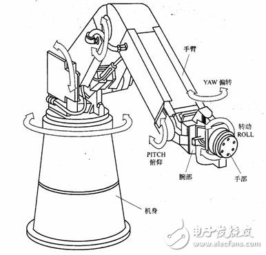
Ball Grid Array (BGA), a type of surface-mount packaging (a chip carrier) used for integrated circuits.
Ball-Grid Array (BGA) Packages Become PCB Design Mainstream
BGA PCB Design Guidelines And Rules
BGA PCB Design Rules
In order to keep up with the technological progress of chip manufacturers, BGA software packages for embedded design have made remarkable progress in the past few years.
This special type of packaging can be decomposed into standard BGA and micro BGA.
Correct BGA partitioning first takes into account uniformity of the partitioning, itself. Because, precise BGA partitioning on a PCB is a crucial design aspect to minimize or eliminate crosstalk and noise, as well as manufacturing issues.
Memory signals need special consideration during BGA partitioning. They need to be away from oscillating signals and power supply switching. This is important because memory signals needs to be clean. If traces carrying these signals are in the proximity of oscillating signals or switching power supply signals, they produce ripples in the memory signal traces, thereby reducing system speed. The system is operational, but at less than optimal speed levels.
BGA PCB Design Guidelines
BGA Design Strategy 1: Define an appropriate exit path
The main challenge for PCB designers is to develop appropriate exit routes without causing manufacturing failures or other problems. Several PCBs need to ensure proper fan-out wiring strategies, including pad and pass size, I/O pin number, layers required for fan-out BGA and line width spacing.
BGA Design Strategy 2: Identify the Layers Required
Another question is how many layers the PCB layout should have, which is by no means a simple decision. More layers mean higher overall cost of the product. On the other hand, sometimes you need more layers to suppress the amount of noise PCB may encounter.
Once the alignment and space width of PCB design, the size of through holes and the alignment in a single channel are determined, they can determine the number of layers they need. Best practice is to minimize the use of I/O pins to reduce the number of layers. Usually, the first two outer sides of the device do not need through holes, while the inner part needs to arrange through holes below them.
Many designers call it dog bones. It is a short path of the BGA device pad, with a through-hole at the other end. The dog bone fan comes out and divides the equipment into four parts. This allows the remaining internal padding to be accessed by another layer and provides escape paths away from the edge of the device. This process will continue until all mats are fully developed.

BGA Package Types
There are six different BGA packages.
1. Moulded Array Process Ball Grid Array (MAPBGA): It is a BGA package which provides low inductance and simple surface mounting.
2. Plastic Ball Grid Array (PBGA): Again, this BGA package provides low inductance, simple surface mounting, high reliability and is cheap.
3. Thermally Enhanced Plastic Ball Grid Array (TEPBGA): Just like its name sound, this BGA package can handle great levels of heat dissipation. Its substrate has solid copper planes.
4. Tape Ball Grid Array (TBGA): You can use this BGA package as a solution for medium- to high- end applications.
5. Package on Package (PoP): It will permit you to put a memory device on some base device.
6. Micro BGA: This BGA package is quite small when compared with standard BGA packages. Currently, you will see 0.65, 0.75 and 0.8 mm pitch size dominating in the industry.
BGA PCB Assembly
Previously, Engineers were not sure whether PCB BGA assembly would be able to achieve the reliability level of traditional SMT methods. However, at present, this is no longer a problem, because BGA has been widely used in Prototype PCB assembly and mass production PCB assembly.
You will need to use reflow methods to solder a BGA package. Because only reflux method can ensure solder melting under BGA module.
We have a wealth of experience handling all types of BGAs, including DSBGA and other Complex Components, from micro BGAs (2mmX3mm) to large size BGAs (45 mm); from ceramic BGAs to plastic BGAs. We are capable of placing minimum 0.4 mm pitch BGAs on your PCB.
PCB BGA Advantages
With PCB BGA, you will get the following advantages:
1. BGA package eliminates the issue of developing small packages for ICs with lots of pins.
2. Again, when compared with packages with legs, The BGA package has a lower thermal resistance when placed on the PCB.
3. Do you know which property causes unwanted signals distortion in high-speed electronic circuits? The unwanted inductance in an electrical conductor is responsible for this phenomenon. However, BGAs have very little distance between PCB and the package which in turn leads to lower lead inductance. Thus, you will get top-class electrical performance with pinned devices.
4. With BGAs, you can effectively utilize your Printed Circuit Board space.
5. Another advantage that will come with BGA is the reduced thickness of the package.
6. Last but not least, you will get enhanced re-workability because of bigger pad sizes.

Via in PAD(VIP) PCB
6 Layer BGA PCB