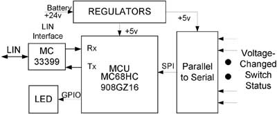
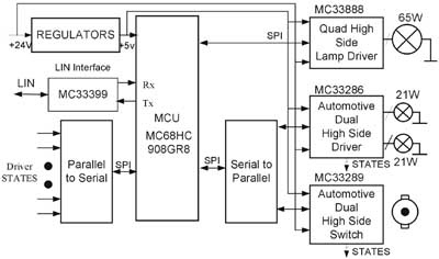
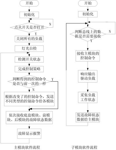
introduction With the rapid development of automotive electronics, the number of electronic control units in modern automobiles has gradually increased. These electronic control units can be roughly divided into three categories: power transmission control (such as engine control and variable speed control), and chassis partial control (such as automobile anti-lock brake system) ABS) and body control. The body control system is mainly to improve driving convenience and riding comfort. The body control system covers a wide range, including lighting control system, door control system, seat control system, climate (air conditioning) control system, dashboard display, etc. This paper selects the control nodes of lights, wipers and some solenoid valves of the chassis to illustrate how the body control system implements a distributed control scheme. system structure The functions to be realized by the system are as follows: * Control all lights on the car. * Control rain Brush low speed, high speed, intermittent work. * Control the operation of the solenoid valve connected to the power take-off, all-wheel drive, inter-wheel and inter-axle differential. * Real-time response to the action of the cab control switch. * Light self-checking function. * Fault diagnosis and positioning capability. The system uses a distributed structure, because the body control system has more control objects and scattered positions. If a point-to-point centralized control method is used, a large number of cables are required to connect the control module and the controlled object. Installation is difficult, and there is a hidden trouble. The distributed system structure can design the control module according to the position of the control object, thereby shortening the distance between the control object and the control module. Each module communicates through the LIN bus. This method requires only one line as a communication line. There are three wires in total, the ground wire and the power wire, which simplifies wiring and makes the system structure clear. At the same time, the distributed system structure increases the flexibility of the system, and can easily add or remove nodes. In addition, the distributed system structure also reduces the quiescent current of the single board and increases the stability of the single board. The system structure is shown in Figure 1. Figure 1 Structure diagram of distributed body control system According to the system functional requirements and structural characteristics, the system is divided into four modules: the main control module and three sub-modules (front module, chassis module and rear module). The main control module is located in the cab of the car, mainly detects the status of the control switches in the cab, and implements the corresponding control strategy according to the status of these control switches, and then sends control commands to each sub-module, while checking the operation of each electrical equipment Status, if there is a fault, the alarm is displayed. The front module is located at the front of the car and mainly controls the electrical appliances in the front of the car, including the lights at the front of the car: high beam lights, low beam lights, fog lights, left and right front turn signals, wipers, fans, heating, emergency alarm, horn work. The chassis module is located in the chassis of the car and mainly controls the work of the solenoid valves connected to the power take-off, all-wheel drive, and the differential between the wheels and the axles. The rear module is located at the rear of the car and mainly controls the electrical appliances at the rear of the car, including the lights at the rear of the car: tail lights, brake lights, left and right rear turn lights. The functional block diagrams of the main control module and sub-modules are shown in Fig. 2 and Fig. 3. Figure 2 Hardware block diagram of the main module Figure 3 Hardware block diagram of submodules The voltage adjustment unit converts the 24V voltage in the car into 5V voltage and supplies it to the single chip microcomputer, power chip and so on. The microprocessor control unit (MCU) uses Motorola's MC68HC908GZ16 and MC68HC908GR8. The microprocessor control unit of the main control module collects the input switch status, completes the corresponding control, and sends the control commands to each submodule through the serial port. The state of the load fed back by the module determines whether there is a fault, and if there is a fault, an alarm is displayed. The microprocessor control unit of each sub-module finishes driving the load, and collects the working state of the load to send to the main control module. The switch state detection unit converts the 24V voltage of the switch state to 5V, and then converts this parallel data into serial data to the MCU, which can greatly reduce the number of MCU pins required. The power drive unit is composed of a power chip and a serial data to parallel data chip. The power chip replaces the traditional relay. Many automotive loads cannot be directly driven by the MCU or low current interface device, and the power chip can output a large current through the MCU control. Drive various loads. Each sub-module can choose different power chips according to the load, MC33286 and MC33888 are used to drive the resistive load, and MC33289 is used to drive the inductive load. The MCU serially outputs the control commands through the I / O port, and the chips converted from serial data to parallel data are sent to the power switch. The fault display unit uses three light-emitting diodes to represent three sub-modules. If a sub-module fails, the corresponding light-emitting diode will light up and the buzzer will alarm. At the same time, the sub-module also uses light-emitting diodes to indicate the status of the load driven by the sub-module, so that it can be seen intuitively which load of the sub-module has open circuit, over current, over temperature, over voltage and other faults. This system uses the communication method of LIN bus. The LIN bus is based on the universal SCI / UART interface, and its cost is lower than CAN communication. LIN can be used as an aid to the CAN communication network. The LIN bus is mainly used in low-speed systems that do not require CAN performance, bandwidth, and complexity, such as & nbsp; Switch type load or position type system includes the control system of the car's rearview mirror, car lock, car seat, car window, etc. LIN is more conducive to the realization of distributed control systems connected to CAN networks in automobiles. LIN has become the first choice for body control system networks due to its low cost. The communication of the system is controlled by the main control module, and the data frame of LIN is defined according to the data content, not the destination address of the data. This definition allows multiple nodes to receive the same information, and data can be exchanged in multiple ways. Data can be sent from the master node to one or more slave nodes, or it can be sent to the master node or other slave nodes through the slave node. Therefore, the communication between the slave nodes does not need to pass through the master node, and the master node can broadcast the information to all nodes in the network. The data communication in this system is mainly that the main module sends control commands to three modules and three sub-modules feed back fault state data to the main module. The system defines several types of data, one is the data received by the three modules, the other is the data received by the front module and the rear module at the same time, the third is the data received by the three modules at the same time, the fourth is the three Data sent independently by the modules. See the system software flow for the communication process. The electromagnetic interference in the car is relatively strong, and the anti-interference ability of the system is high. The system is designed with anti-interference in hardware and software. On the hardware, the photoelectric isolation circuit is used on the communication line, and the DC-DC isolation is also used on the power supply. A decoupling capacitor is designed between the power supply and ground, which can filter out high-frequency noise from the power supply. In the layout of the printed circuit board, the digital circuit and the power drive circuit are reasonably separated to minimize the signal coupling between each other. In software, the system uses watchdog technology, which increases the reliability of the system. The system software flow chart is shown in Figure 4. Figure 4 Software flow chart Conclusion This design scheme realizes the basic functions of the system, and has a simple structure and low cost. This design idea is also applicable to cars and medium-sized vehicles.
The LC connector was the first small form factor connector on the market.
The use of a high performance 1.25mm ferrule gives the connector extremely high performance acteristics. Fiber Optic Pigtail Splicing,Optical Pigtail,Pigtail LC,LC Pigtail Multimode Chengdu Xinruixin Optical Communication Technology Co.,Ltd , https://www.xrxoptic.com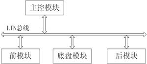
LC connector comprises of a polymer body and a ceramic ferrule/sring/crimp barrel assembly plus a crimp over sleeve and rubber boot. These connectors are suitable for 900um and 2mm cables.
The connector is precision made and manufactured to demanding specifications. The combination of a ceramic ferrule and a precision polymer housing provides consistent long-term mechanical and optical performance.