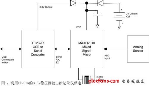
Many medical applications require portable self-powered equipment that does not require external power and data cables. The most obvious example is the portable data recorder that patients carry to measure heart rate, body temperature, and other health indicators. Of course, there are still many complex applications that require a small battery device to achieve safety redundancy and device monitoring, even if powered by an external power source, such as hospital wards, patient rooms, environmentally controlled laboratories, or storage equipment environmental parameters (including temperature And humidity) require continuous monitoring; in addition, the installation and use of portable devices are more convenient and flexible than those requiring external power supplies and network cables. In some cases, such as medical equipment that needs to be carried by patients, temperature detection equipment for cold storage, etc., it is impossible to connect the power cord and network cable at all. What functions are required for portable medical equipment? First of all, you must bring your own power supply. Usually can be powered by rechargeable or non-rechargeable batteries, although there are other ways (such as solar power), but this depends on the voltage and current requirements. No matter what kind of power supply is used, the efficiency of the power supply must be high enough, and the battery-powered portable device should enter the "sleep" mode to reduce power consumption as much as possible when it does not need to work at full load. The sleeping device can be triggered by an external signal or periodically Will be "awakened", and then increase the calculation speed (of course, the power consumption will increase) to enter the normal working mode. The device should also have some working modes between full-load operation and "sleep" mode to perform some simple tasks (such as accessing memory or refreshing LCD and LED display data), because the device usually only works under certain conditions Full load computing capability is required (such as filtering and decoding of sensor data), so that a certain degree of balance can be made between power consumption and computing speed. Even though portable devices support wireless communication, they are not always guaranteed to be able to access wireless networks. Depending on network conditions, the device works in a wireless network environment at a certain moment, and may be moved to an environment without a wireless network at the next moment, or the wireless network may be temporarily shut down due to a power failure. In these cases, if the device itself does not support wireless communication, the device needs to store the data collected at any time for future upload to the upper-level system for data processing. There are some key data (such as environmental safety failure data, configuration data or device drivers) that must be stored safely, even if the battery fails or is removed. Other characteristics of portable devices depend on specific application requirements. Data can be collected directly through analog sensors or read through a local area network access subsystem. Portable devices can only collect data passively or can actively sound alarms under specific conditions Or signal someone an alarm. Some simple data acquisition devices require no user intervention before uploading data, while others (such as handheld blood glucose meters or wristband heart monitors) may require additional input and output devices instead of the host system to change configuration or view data . Using MAXQ2010 to design portable data recorder Although there are many microcontrollers to choose from in the industry, Maxim's MAXQ series low-power mixed-signal RISC microcontroller MAXQ2010 has features that are ideal for designing battery-powered data acquisition equipment. MAXQ2010 has very low power consumption, very high MIPS / mA ratio, only needs a small battery current to support portable applications, integrated 12-bit 8-channel ADC can collect many types of sensor data, and also supports many types of local serial interfaces (Such as I2C, SPI, synchronous / asynchronous UART), can be used to access the host system and serial non-volatile storage devices, or communicate with other subsystems in the device. MAXQ2010 can dynamically adjust the clock frequency to change the power consumption according to the current task's computing power requirements, and when it has processed all data and events, the portable device can enter the lowest power sleep (stop) mode until it is applied again wake. The core voltage of MAXQ2010 is only 1.8V, which can greatly reduce power consumption. I / O with 3V independent power supply can communicate with external high-voltage logic. If you want to use a single power supply such as a 3V button lithium battery and do not want to use dual power supplies, you can power the core voltage through a built-in integrated voltage regulator. In stop mode, the regulator can be turned off to reduce power consumption. MAXQ2010 can read data from the sensor through a variety of ways. If you are collecting analog sensor data, you can use the built-in 12-bit multi-channel ADC to support 8-channel single-ended input. The data collected by MAXQ2010 from external sensors can be stored in RAM powered by a backup battery or in internal flash memory as needed. The on-chip 32kHz-based real-time clock (RTC) can also work in stop mode, providing time stamps for data as needed. If the user needs to input data or display information to the user, MAXQ2010 can achieve it. It has a set of general-purpose input / output pins (56 in the largest package) that can drive LEDs, read mechanical switch settings, or scan through rows and columns Way to connect the switch matrix. MAXQ2010 also has an LCD controller that can directly drive a 3V segment LCD. It supports up to 1/4 cycle multiplexing (COM1 ~ COM4). Its largest package provides 40 dedicated drive pins, which are multiplexed by 4 times. It can drive 160-segment LCD display in mode. Design example of data recorder based on MAXQ2010 Like many electronic devices used to collect or store data, a data logger based on MAXQ2010 uses a USB interface to communicate with a host computer (such as a personal computer). However, since MAXQ2010 itself does not have a USB interface, we use the FT232R chip of FTDI to realize the transfer between USB and UART. Using FT232R can bring many benefits to the data logger design. First of all, when the USB bus is active, the data logger can use the FT232R's 3.3V regulator output power supply, only need a pair of diodes to achieve automatic switching with battery power supply, because the regulator output (less than 0.2V diode before (Voltage drop) voltage is always higher than the battery voltage minus the diode voltage drop, so that when connected to the USB bus, the recorder can be powered by the USB Vbus without using the battery. Two diodes (Figure 1) are used to prevent charging the battery, and the output capacitor is used to reduce the impact of load transients on the battery. Secondly, MAXQ2010 can use one of the two serial ports (UART) to communicate directly with the application running on the personal computer without any additional drivers. The two serial ports are connected through a virtual COM port established on the USB interface. This design uses the FLQ of MAXQ2010 based on a 32kHz crystal as its own clock source (and can provide a time base for RTC if needed), and its cost is much lower than the cost of other crystals or resonant circuits. The FLL circuit is equivalent to a frequency multiplier with a frequency multiplication factor of 256, which changes the 32kHz crystal oscillation frequency to 8.388MHz as the clock for MAXQ2010. To calculate how much current the MAXQ2010-based data logger consumes, consider performing the following operations: First, an external signal (such as a button or sensor voltage suddenly increases) wakes the microcontroller from stop mode; the system then passes a single-ended ADC The channel reads the analog sensor voltage and stores the collected sensor voltage value in the data RAM; at this time, in order to save power, the microcontroller returns to the stop mode, and after about 60 seconds, the microcontroller is woken up again (back To step 1). Therefore, calculating the average current consumption and estimating the battery life requires substituting the following parameters of the microcontroller into equation (1): tAcTIve (the time required to complete all the above operations, including the time to enter the stop mode), iAcTIve (typical during the above operations Current value), tStop (time to stay in stop mode), iStop (typical current at stop mode), tExit (time required to wake up from stop mode), iExit (typical current at wake-up). (tAcTIve & TImes; iActive) + (tStop × iStop) + (tExit + iExit) tActive + tStop + tExit According to the value of the above parameters, the average current can be calculated to be about 202nA; that is, if the power supply is an ordinary CR2032 lithium coin battery, the battery life can be estimated to be 1138 hours. The characteristics of batteries produced by different battery manufacturers will be different. The voltage drop of a CR2032 battery in a 90% discharge interval does not exceed 0.3V, which means that before the battery voltage drops to 2.7V (after a diode voltage drop is 2.5 V, to meet the minimum voltage when working with a single power supply), the microcontroller can work for 1024 hours. Many measures such as increasing battery capacity or quantity, using rechargeable batteries, or automatically charging when connected to USB are used to extend battery life. Generally, the average current is only slightly higher than the standby current in stop mode. This is because the time in stop mode is much longer than the program running time, and the current in stop mode plays a leading role. The program loop body code can be expanded, such as measuring multiple sensor values ​​or adding other functions without significantly changing the battery life. Of course, the use of other peripheral functions, such as LCD display, LED indicator or serial port, will increase power consumption. Designers need to consider the power consumption that these functions may increase when calculating the actual battery life. Transformer For Renewable Energy Transformer For Renewable Energy, Solar Transformer,Wind Mill Transformer, Energy Station Hangzhou Qiantang River Electric Group Co., Ltd.(QRE) , https://www.qretransformer.com