This paper uses the power carrier technology to design a ward call system. With the development of power carrier technology, it has become possible to use low-voltage power lines as transmission media, and use spread spectrum, digital coding, single-chip control and other technologies to realize ward calls. 1 Basic requirements for ward call system Parabolic Reflex Reflector,Parabolic Grow Reflector,Aluminum Lamp Reflector,Safety Lighting Covers Yangzhou Huadong Can Illuminations Mould Manufactory Co., Ltd. , https://www.light-reflectors.com
The clinical help call is an important means of transmitting clinical information. The ward call system is an emergency call tool for patients to request a doctor or nurse for diagnosis or care. It can quickly transmit the patient's request to the doctor or nurse on duty, and is in the monitoring center of the duty room Leaving accurate and complete records on the computer is one of the necessary equipment to improve the level of care in hospitals and wards. The quality of the call system is directly related to the safety of the patients, and has always been widely valued by major hospitals. It requires timely, accurate, reliable, simple and feasible, and is conducive to promotion. The bed call system with the functions of call, ringing, display queuing, priority setting, and storage record designed by power line carrier communication technology, single-chip multi-computer communication and computer monitoring and management technology meets the requirements of hospital ward management and care.
2 ward call system design
2.1 System composition and working principle
The ward call system consists of several call sources (generally one for each bed), a modem carrier module, a coupling circuit, and a monitoring system, as shown in Figure 1. When the call source has a call signal, there is a corresponding sound and light call signal indication on the monitoring system, and the call number can be displayed. If the parallel bus expansion method is used, the wiring between hundreds of call sources and the host is too complicated, so this system uses the serial communication function of the single-chip microcomputer to make the signal from the host to each slave through the power line carrier modulation and demodulation module. After ~ 220V civil power line transmission, two-way data transmission between the master and slave is realized. 
Figure 1 System block diagram
The system adopts a master-slave structure, and the monitoring system (host) is placed in the doctor's duty room (which can be connected to the computer through the interface circuit to form a monitoring center) .When the bed has a call request, it will sound and light alarm and display the position of the bed on the display . The call source (slave) is placed in the ward. When the patient has a call request, press the request button to call the duty room and light the call indicator. The master and slave are connected together by power lines. When the master and slave communicate, the master sends address information to each slave in turn. Each slave receives the address information from the master.If it is the same as its own address, it sends its own alarm information to the master. The host sends an empty number (00).
2.2 Introduction to SC1128 spread spectrum communication chip and transceiver circuit
The SC1128 chip is a dedicated spread-spectrum modulator / demodulator circuit developed for the power line carrier communication market. Due to the adoption of new technologies such as direct sequence spread spectrum, digital signal processing, and direct digital frequency synthesis, this circuit has strong anti-interference and anti-attenuation performance in power line communication. The SC1128 chip integrates spread spectrum / de-spread, modulation / demodulation, D / A conversion and A / D conversion, built-in electronic watch, output drive, input signal amplification, watchdog, operating voltage detection, and MCU Serial communication and other functions. The chip can play a role in reducing system cost and improving system functions in a small multifunctional application system.
The block diagram of the transceiver circuit composed of the SC1128 chip is shown in Figure 2. The signal enters the SC1128 chip from the power line through the coupler, bandpass filter and pre-amplifier. After processing, it is sent to the power line through the power amplifier and coupler to complete the signal transmission and reception on the power line. Box one is a coupling coil, which can couple the signal transmitted in box three to the power line; and can couple the signal received on the power line to box two. Box 2 is the pre-stage receiving circuit, which filters and amplifies the received signal and sends it to SC1128's first-stage operational amplifier (13 feet) for processing. Box 3 is a power amplifier, which amplifies the power of the phase-modulated signal sent from the 24 pin of SC1128 and sends it to the power line through the coupling coil. Box 4 is part of the SC1128 internal analog signal processing circuit, including three-stage operational amplifier, of which the gain of the first-stage op amp is adjustable. 
Figure 2 Block diagram of the transceiver circuit composed of SC1128 chip
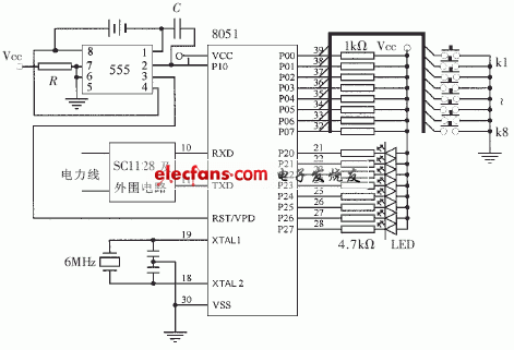
The call source is composed of 8051 single chip microcomputer (slave), SC1128 spread spectrum communication chip and some peripheral circuits, as shown in Figure 3. Eight request button switches are connected to the P0 port of the microcontroller 8051. When a button is pressed, the input state of the P0 port corresponding to the button is 0. When the MCU confirms that the host calls the address of the machine, it scans the status of the 8-bit I / O port on the P0 port, and once a key is pressed, it immediately sends the request information corresponding to the P0 port to the host, and waits for the host's confirmation. When the host returns the correct information, the corresponding LED indicator is driven through the P2 port to indicate which request signal was successfully sent. The eight request button switches are respectively numbered, and each switch represents a kind of request information, which is defined by the user. 
Figure 3 ward call source circuit
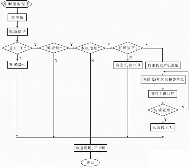
The P1.0 and RST / VPD ports of the 8051 microcontroller are connected to the backup power supply and the power-down protection circuit to ensure that the system can be used normally in the event of a power failure such as a power failure. If the system has detected the "power failure is about to occur" signal, the signal requests an interrupt to the host through the external interrupt INT0, the host responds to the interrupt and sends the relevant data to the internal RAM to save, and then writes "0" to P1.0, which is caused by P1 The low level on the .0 pin triggers the 555 timer, and the output pulse of the 555 timer depends on R, C, and VCC. If the 555 timer expires, the VCC is still normal, which indicates that the "power failure is about to occur" signal is an erroneous alarm signal, then the positive pulse output by 555 is added to the RST / VPD to reset the host and restart operation; if RST / VPD At the end of the 555 timing, it really becomes low, then the 555 timer outputs a high level under the P1.0 low level trigger and adds it to the RST / VPD as a backup power supply until VCC returns to normal, and then maintains a period of time The positive pulse width time determined by C. Appropriate R and C values ​​should be selected so that after the main power supply VCC returns to normal, there is sufficient power-on reset time to allow the host to resume normal operation after a reliable reset. The 8051 clock adopts the on-chip clock oscillation mode, and externally connects quartz crystal (6MHz) and oscillation capacitor to the XTAL1 and XTAL2 pins. The serial ports RXD (P3.0) and TXD (P3.1) communicate with the host through the SC1128 chip and power line. The flow chart of the call source interruption program is shown in Figure 4. 
Figure 4 Flow chart of call source interruption program
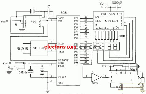
The monitoring system consists of 8051 single-chip microcomputer (host), display device, alarm circuit, SC1128 chip and some peripheral circuits, as shown in Figure 5. The three I / O lines of the P0 port of the 8051 single-chip computer provide the clock signal, enable signal and serial data required by the MC14499. The MC14499 drives and controls four LED eight-segment displays. And the alarm category, where the first three LEDs indicate the bed number, and the latter indicates the alarm category.
P2.0 port drives the alarm speaker through the non-door. The host is provided with a button key K, which is directly connected to INT0. K is used to cancel the alarm sound and the alarm source indicated by the LED digital tube. The standby power supply, power-off protection circuit and clock oscillation mode adopted by this circuit are the same as the call source circuit. The flow chart of the monitoring system program is shown in Figure 6. 
Figure 5 monitoring system 
Figure 6 Flow chart of the monitoring system program 
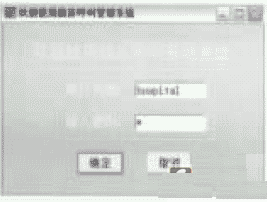
Figure 7 login interface 
Figure 8 Management interface
2.5 ward call management system software design
The above-mentioned parts of the circuit combination have been able to complete the ward call function. In order to improve the system and enable the call system to be combined with the bed information management, the ward call management system software has been designed to form a ward monitoring center composed of a computer and corresponding interface circuits . The call information is processed by the microprocessor and input to the computer through the interface circuit, and then the call information and patient information are managed through the computer software. Here only introduces the ward call management system software based on POWER BUIDER9.0 as follows: This system is equipped with protection functions, non-management personnel can not enter the system to obtain information, only to obtain the password to enter the system's information interface. The login interface is shown in Figure 7.
This system has add function, edit function, query function, delete function, page turning function and exit function. After detecting the correct password, the system enters the management interface (as shown in Figure 8), which includes functions such as the management of the patient's basic information, display of call information, classification, and storage query.
The basic information management of the patient is to establish the patient's data information in the database, the database is composed of tables. A table is a method of storing organized data in a database. The table has a pre-defined structure and stores data conforming to this structure.
The host of this system adopts the query mode and the slave adopts the interrupt mode. The system has the following characteristics:
(1) When the address code sent by the monitoring system received by the call source is consistent with the local address code, the alarm status data of the alarm point is transmitted to the monitoring system; if it is not the same, no response will be given. The single-chip microcomputer continuously inspects the detection points to ensure that only one call source sends an alarm signal at a certain time, which solves the problem of channel contention and truly realizes multi-way calls.
(2) This system adopts SC1128 chip with modulation and demodulation function and communication network formed by power line. It has the characteristics of simple structure, low cost, flexible and reliable working mode, and strong anti-interference ability.
(3) This system adopts the information monitoring and management system software designed by POWER BUIDER9.0, which has the characteristics of friendly interface, strong confidentiality, and strong usability. The operator can master it after short-term training.
In short, compared with other existing call systems, the call system is reliable, simple, and practical, and is suitable for use by hospitals at all levels. Especially for the hospitals that have been built and need to add call system, the ward call system based on power line should be the first choice.
Ward call system design
2.3 Design of the call source circuit
2.4 Design of monitoring system