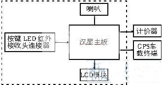
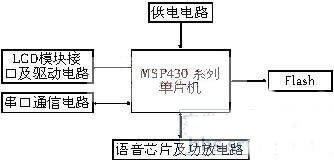
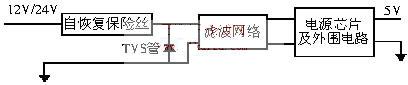
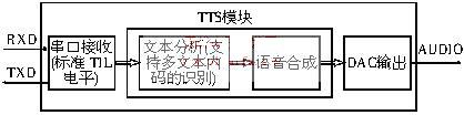
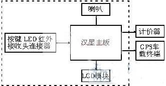
1 Introduction This article refers to the address: http:// In recent years, GPS navigation and positioning technology is constantly developing, and more and more vehicles are equipped with in-vehicle GPS terminals. Today, car GPS terminals have become an important part of the urban traffic management network. However, since the installation of the vehicle-mounted GPS terminal, the user has affected the user's use and the popularity of the vehicle-mounted GPS terminal due to the lack of friendly human-computer interaction equipment, which limits the function expansion of the vehicle-mounted GPS terminal product. By adding a Chinese character display terminal, the user can use the car GPS terminal more conveniently, which facilitates the center to perform dispatch management and make up for the deficiencies of the previous products. 2 embedded Han Xian composition Figure 1 Car GPS system structure The function of embedded Hanxian is mainly to communicate with the GPS vehicle terminal and the meter through the serial port, receive and process the GPS positioning signal sent by the GPS vehicle terminal and the relevant operational data sent by the meter, and let the user display the Hanxian through the infrared remote control and the button. Make settings and operations, then display the corresponding content on the LCD module and provide voice services. The embedded Hanxian consists of the following components: Hanxian motherboard, LCD module, infrared receiver, buttons, speakers, LEDs and connectors. 3 motherboard hardware part Figure 2 Han Xian structure diagram The embedded Hanxian motherboard consists of the following parts: parallel port flash, power supply circuit, LCD module interface and drive circuit, serial communication circuit, watchdog power Road and voice chips and power amplifier circuits. 3.1 MSP430 series MCU MSP430 series MCU is a 16-bit MCU developed by TI Company. Its outstanding feature is ultra-low power consumption, which is very suitable for various power requirements. It is the power consumption of all internal integrated flash memory (Flash ROM) products. The lowest, consumes only one-fifth the power of other Flash MCUs. At 3V operating voltage, its current consumption is less than 350uA/MHz, and the standby mode is only 15 uA/MHz. It has five energy-saving modes. Its 64K program space guarantees enough code length, and the internal FLASH that can be written during program execution can be used to store important data such as center number, phone number and GPS vehicle terminal settings. The MCU has anti-ESD protection and strong anti-interference ability. Online programming, program update is convenient. The simulator is simple in structure and can be made by itself. This series of industrial-grade single-chip microcomputers has an operating temperature range of -40 to +85 degrees Celsius, which can meet the requirements of automotive equipment applications. 3.2 Power supply circuit In order to be compatible with the 12V and 24V voltages provided by different car batteries, the voltage converter used in the power supply circuit should be able to meet the input voltage between 9V and 36V. Due to the harsh environment of the vehicle, the battery power supply fluctuates greatly. In order to prevent the high current caused by external interference from burning out the internal components, the self-recovery fuse can be connected in series at the power input end. The basic power consumption of the motherboard is about 50mA. When the LCD backlight is lit, the power consumption is about 180mA. Therefore, a self-recovery fuse with a fuse current of 350mA can be selected to meet the requirements. In order to prevent the microprocessor or the single chip from malfunctioning or damage caused by the instantaneous pulse, such as static interference, a TVS tube can be connected in parallel with the positive input terminal of the power supply. Since the power supply voltage of the vehicle battery is 12V or 24V, it can be selected according to the actual situation. . Figure 3 power supply circuit 3.3 Memory Flash needs to save GPS location information, key points, fonts, call history, short messages, operational data and other data. The Flash capacity requirements are analyzed as follows: 3.3.1 The font library requires approximately 800K bytes. 3.3.2 GPS positioning information needs to be saved as a driving record. At present, most GPS modules send GPS positioning data once per second. If each item is reserved as a driving record, it has no practical significance, so it can be used every one to ten. The positioning data is retained once in minutes, so that 10,000 items can save at least one week of driving records, which meets the needs of practical applications. The positioning information includes: time, longitude, longitude identification, latitude, latitude identification, speed, direction, status, and additional information. Positioning information calculation: 10000 × 48 bytes = 480000 bytes 3.3.3 For special requirements such as speed limit prompts, road segment prompts, and area prompts, you can pre-store the positioning data information of these key points or polygons, and the positioning information will be received when the vehicle passes, arrives, and leaves these areas during driving. Compare it with the voice broadcast to identify and prompt. Key information includes: key entry time, exit key time, bottom left latitude, lower left longitude, upper left latitude, upper left longitude, lower right latitude, lower right longitude, upper right latitude upper right longitude and other signs Bit and so on. Key point information calculation: 52 bytes × 200 = 10400 bytes (save 100 key points, reserve 100 key points capacity) Polygon information includes: vertex number, vertex longitude, vertex latitude and other information. Polygon: 10 × 9 vertices × (2+10 + 11) = 2070 bytes (maximum 10 9-sided) Therefore, the capacity should be at least 1MB, and it is better to use parallel port communication Flash to meet the high-speed data transmission with MSP430 series MCU. 3.4 voice chip and power amplifier circuit In order to shorten the development cycle, consider integrating a complete speech synthesis system inside the processor. Take the voice chip of Keda Xunfei as an example, the chip supports the synthesis of any Chinese text. The Chinese code can use GB2312 or Unicode two encoding methods, the level logic is TTL level, and the command sent by the host computer is received through the serial port (UART). And data, commands and data are encapsulated and sent in frames, allowing a maximum length of 200 bytes to be sent. After receiving the command or text synthesis, the voice chip sends feedback information to the MCU through the serial port TXD2. The MCU can know whether the chip has correctly received the command and whether the chip has completed text synthesis by receiving feedback from the chip. When the chip READY signal pin is at a low level, it indicates that the chip is in the standby ready state; when it is at a high level, it indicates that the chip is in a text synthesis state. Voice through the 10bit DAC analog audio output, the peripheral power amplifier circuit using the most commonly used LM386 power amplifier circuit can meet the requirements. Figure 4 Speech chip block diagram 3.5 Other peripheral circuits Since the current domestic car GPS terminal and meter are basically connected to the Chinese character display terminal by means of serial communication, according to different vehicle terminals and meter, the corresponding serial communication mode must be adopted. Consider the conversion circuit circuit and current loop of MAX202. Circuit or other solution. The principle of the current loop circuit is as follows: Figure 5 schematic diagram of current loop circuit MCU and Flash are best to use a 3.3V power supply low-power chip, so it is necessary to connect with the LCD module through the 3.3V ~ 5V level conversion chip as the core drive circuit, or use the appropriate solution according to the LCD module. 4 Conclusion Today, the car GPS technology is very mature, the development trend of the car GPS system is to provide more friendly human-computer interaction function and better service. The embedded Chinese character display terminal can realize the expansion of the vehicle terminal through the serial port, provide a friendly human-computer interaction interface for the vehicle GPS terminal, and personalize the setting, which is greatly convenient for the user to use, and expands the functions and resources of the vehicle GPS terminal. Can provide users with a richer service content. Therefore, the embedded Chinese character display terminal will greatly promote the popularization of the car GPS system and promote the development of the car GPS system. references: [1] Hu Dake edited. MSP430 series 16-bit single-chip principle and application. Beijing: Beijing University of Aeronautics and Astronautics Press, 2000 [2] Hu Dake edited. MSP430 series FLASH type 16-bit single-chip microcomputer. Beijing: Beijing University of Aeronautics and Astronautics Press, 2001 [3] Beijing Juli Technology Co., Ltd. GPS communication protocol between meter and vehicle terminal. Beijing: Beijing Juli Technology Co., Ltd., 2005 DC EMI Filter,DC RFI Filter,DC Line Filter,DC Noise Filter Jinan Filtemc Electronic Equipment Co., Ltd. , https://www.chinaemifilter.com