I. Introduction to intelligent driverless car computer control system This article refers to the address: http:// 1. Introduction to intelligent driverless driving Intelligent driverless car is a comprehensive system integrating environment sensing, planning decision-making, multi-level assisted driving and other functions. The operation of the vehicle can be regarded as a complex and variable relationship between multiple inputs, multiple outputs and input and output. The control process of complex nonlinear systems with uncertain multi-interference sources. Drivers must accept information such as access, congestion, direction, pedestrians, etc., as well as information such as vehicle speed, lateral offset, yaw rate, etc., and then judge and analyze and make decisions with their own driving experience. In comparison, the manipulation action that should be done is determined, and finally the movement of the vehicle is completed by the body, hands, feet, and the like. Therefore, the driver's human factors account for a large proportion of the entire driving process. In the event of a driver's long drive, fatigue driving, and misjudgment, it is easy to cause a traffic accident. Second, the system's control requirements (1) The system center control component (single-chip microcomputer) has high reliability, strong anti-interference ability, and the working frequency can reach up to 25MHz, which can guarantee the real-time performance of the system. (2) The system should adopt anti-interference technology in software and hardware, including optical isolation technology, electromagnetic compatibility analysis, digital filtering technology, etc. (3) The system has real-time power supply monitoring and automatic power-off function in undervoltage state. (4) The system has a fault self-diagnosis function. (5) The system has a good humanized display module, which can display important parameters of the current state of the system (such as smart car speed and power supply voltage) on the LCD. (6) When the driving force of the car in the system is 500N, the car will reach a maximum speed of 10m/s in 5 seconds. First, the overall system design 1, the overall structure of the system The whole system is mainly composed of car model, model car control system and auxiliary development system. The functional modules of the smart car system mainly include: control core module, power management module, path identification module, rear wheel motor drive module, steering servo control module, speed detection module, battery monitoring module, trolley fault diagnosis module, LCD data display module And debugging auxiliary modules. Each module includes both hardware and software. The hardware provides hardware entities for system work, and the software provides various algorithms for the system. 2. Control and execution agencies The smart car mainly simulates the actuator through the self-made trolley. The self-made trolley has a length of 34.6cm, a width of 24.5cm, a weight of 1.2kg, a sampling period of 3ms, and a detection accuracy of 4mm. In the control mechanism, the main control core uses the freescale 16-bit microcontroller MC9S12DG128B. The system is designed on the basis of CodeWarrior software platform, using C language and assembly language mixed programming, providing powerful auxiliary modules, including battery detection module, trolley fault diagnosis module, LCD data display module and debugging auxiliary module. In the path identification module, the system utilizes the fuzzy inference engine provided by the freescaleS12 series of single-chip microcomputers. 3. Control law Because the system motor control module controls the motion state of the car, its characteristic parameters vary greatly at different stages, so the digital PID controller is adopted. The controller has mature technology, simple structure and easy adjustment of parameters, and does not necessarily require the exact digital model of the system. 4, the main functions of each module of the system Control core module: use freescale 16-bit microcontroller MC9S12DG128B, the main function is to complete the processing of the acquisition signal and the output of the control signal. Power Management Module: Voltage regulation of the battery to provide a reliable voltage for normal operation of each module. Path identification module: completes the collection, preprocessing and data identification of the runway information. Rear wheel motor drive module: Provides reliable drive circuit and control algorithm for the motor. Steering gear control module: Provides reliable control circuit and control algorithm for the steering gear. Speed ​​detection module: Provides accurate speed feedback for motor control. Battery monitoring module: Real-time monitoring of battery power for scientific use and protection of the battery. Car fault diagnosis module: Quick and accurate diagnosis of car faults. LCD data display module: Displays important parameters of the current state of the system. Debug auxiliary module: make the car debugging more convenient. 5, the system development platform System software development platform uses CodeWarrior for S12 Second, system hardware and software design 1, the system hardware design The system hardware system block diagram is as follows: The following hardware circuits are designed separately for each module: (1) Power Management Module: The function of the power management module adjusts the voltage of the battery to provide a reliable working voltage for each module to work properly. The power management module is composed of 7.2V, 2000mAh nickel-cadmium battery and LM2576 (5V), LM317 (6V) regulator chip. (2) Microprocessor: using microprocessor MC9S12DG128 (3) Path identification module: Infrared transmitting tube and infrared receiving tube and Darlington tube ULN2803A are used as path recognition sensors. Using a two-row sensor strategy, the first row of sensors is dedicated to identifying the various feature points of the path and the memory path, and the second row of sensors is specifically used to identify the starting position and the intersection, since the functions of the different sensors are different, Their arrangement and installation location are also different. (4) Rear wheel drive and speed detection module: The model for driving the DC motor is RS-380SH, and the output power is 0.9W—40W. The motor drive part uses two full-bridge drive circuits composed of MC33886, which can control the reversal of the motor to achieve the purpose of braking. (5) Steering gear module: It can be achieved with a steering gear when it is necessary to operate. The design of the steering gear used in this design is HS-925 (SANWA), the size is 39.4*37.8*27.8, the weight is 56kg, the working speed is 0.11sec/60 (4.8V), 0.07sec/60 (6.0V), the stalling torque 6.1kg. (6) Power supply voltage detection module The smart car is powered by a nickel-cadmium battery. The main components used in this module are the optocoupler chip TLP521-2 and the operational amplifier LM324. (7) Liquid crystal display module: LCD controller HD44780. (8) Auxiliary debugging module (infrared remote control): This module mainly uses infrared receiver HS0038A and infrared remote control for remote control. (9) Fault diagnosis module: Using the SCIO port of the single-chip microcomputer, it is connected with the host computer through the RS-232 interface. Through software programming, the car continuously sends the code to the upper computer, and the fault source can be diagnosed immediately through the fault code. 2, the system software design (1) Rear wheel drive motor control algorithm The digital control controller's continuous design technology PID control algorithm is used to control this part of the circuit. The transfer function of the PID controller is: Set Kp= 1500 for testing. At this time, the simulation static value and static error and rise time have basically met the system requirements, so that it is possible to adjust the system characteristics by continuously increasing the proportional coefficient, and theoretically, the integral link can be omitted. However, as the proportional coefficient increases, the dynamic process will be unsatisfactory, and its dynamic changes will be too fast, which will bring physical discomfort to the driver and increase the points: The addition of the integral link can adjust the static error of the system. Set Kp=1000, Ki= 50 system basic implementation design requirements So in summary, the transfer function of the PID controller we designed is: The sampling period is T=0.1s. The system is then designed using the discrete design steps of the digital controller. Through the previous analysis, we know that the continuous transfer function of the controlled object is: . Where m=1000 and b=50. Because the transfer function of the zeroth order keeper is: . So the pulse transfer function of the generalized object is: Ten times the unit pulse input signal, ,select . In the ten step unit step signal, when the sampling period is 1 s, only one beat output can track the input, and the error is zero, which is very good to meet the system design requirements. (2) Software design of path identification module Path recognition mainly uses the fuzzy inference engine inside MC9S12DG128B to realize the basic knowledge of fuzzy logic. (3) Digital filtering technology In the digital closed-loop control system of the motor, the measured value In the design of this system, the moving average filtering method is adopted. The moving average filtering method does not calculate the measured value once, only needs to be sampled once, so the data processing speed is greatly accelerated, which is very suitable for real-time control. The moving average filtering method stores the sampled data in the order of the sampling time in the RAM, sequentially moves the data before each calculation, removes the first sampled data before the queue, and then adds the latest sampled data to the data. The tail of the queue to ensure that there are always n data in the data buffer, and the data is still arranged in the order of sampling. At this time, the arithmetic mean of each data in the queue is calculated, and the arithmetic mean is the measured value. (4) Steering servo control algorithm Steering gear control is a very important part of the smart car system. The control of the steering gear also directly affects the control effect of the car. The control signal of the steering gear is 20ms pulse width modulation signal, and the pulse width is from 0.5ms to 2.5. Ms, the position of the corresponding steering wheel is 0-180 degrees, which varies linearly. That is to say, given a certain pulse width, its output shaft will remain at a corresponding angle, no matter how the external torque changes, it will change the output angle until it is given a pulse signal of another width. Go to the new corresponding location. (5) Speed ​​detection software design The speed sensor uses an infrared through-beam sensor that senses the speed-dependent pulses and then identifies the pulses. There are two ways to identify, one is to measure the speed of the car by measuring the width of the pulse, and the other is to identify the speed of the car by counting the number of pulses in a certain period of time. This design uses the latter method. In this design, the two resources inside the MC9S12DG128B are utilized, which are RTI interrupt and input capture interrupt: the RTI interrupt can control a certain time, this time is fixed; the capture pulse is calculated by input capture interrupt The number is finally reflected by the number of pulses captured during this time. First, the system design summary The intelligent vehicle control system has a high degree of intelligence, simple operation and reliable performance, and adopts a special single-chip control system to improve the reliability of the system; the degree of intelligence is high, and to a certain extent, basically no manual operation is required; LCD liquid crystal display is adopted. The degree of human-computer interaction is high. Guangzhou Ehang Electronic Co., Ltd. , https://www.ehangmobile.com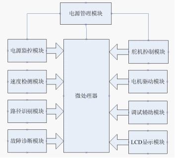
It is obtained by sampling the output of the system. It forms a deviation signal from the difference between the given value r(t)
, so, measured value
It is important data to determine the size of the deviation. If the measured value does not truly reflect the output of the system, then the control system loses its effect. In practice, the measured value of the motor output is often mixed with interference noise. Using the measured value mixed with interference as the control signal will cause malfunction, and the system will also cause system oscillation in the system with differential control link, which is extremely harmful.
, it implements every sample, it calculates one
.