Discuss the application of near-field analysis in EMC. I believe that we have a certain understanding of EMC. We must first make the electromagnetic waves so invisible and invisible. Today I will introduce a method, how to make These electromagnetic waves become intuitive, and that is near-field analysis.
EMC status
First of all, I will introduce the status of EMC, which will enable you to better understand the necessity of near-field analysis. The second one will introduce the equipment and methods of EMC near-field analysis. We will give some practical case studies in the third part. Finally, we will make a summary to better review these contents.
First, let's take a look at the state of EMC research. We also know that more and more digital devices are entering our lives. These digital devices are a source of noise for the entire environment. These noise sources are mutually influential. Under such circumstances, the electromagnetic environment has become quite complicated. When these noise sources have not been completely solved, we also face internal noise problems. For internal noise problems, we have selected notebooks and mobile phones. We all know that there are a lot of digital circuit modules. These digital circuit modules play a digital product we mentioned earlier. It is undoubtedly a source of interference. At the same time, we are more and more wireless communication devices are integrated for wireless demand. In the circuit, we look at the mobile phone, the mobile phone is originally a communication device, the main function is communication, mobile phone communication and GPS function, with our pursuit of handheld functions, more and more chips are integrated, even us Increased resolution requirements, resulting in more and more noise sources integrated into mobile phones In, thus causing internal electromagnetic environment of digital products become more complex, since there is an antenna RF components, our entire internal environment becomes quite cumbersome, not easy to solve. Such a problem, we call it the problem of EMC inside the system. Since the internal antenna receives this kind of noise, the antenna receiving signal does not distinguish whether it is a useful signal or a useless signal. When these noises become high, it will make us The sensitivity of the acceptance is relatively low, which makes our wireless devices unable to connect. This is the principle of the EMC problem inside the system we mentioned.
Internal system noise energy
After we understand the internal system principle of EMC, let's look at another important question. How strong is the noise energy of this internal system? We can see that our digital TV signal is between -105 and -170. We need another way to monitor these noises. Next we will introduce such a method, near-field measurement.
First, we will use such a magnetic field probe to collect the magnetic field energy. The energy we collect through the magnetic field probe. Because we know that the current integration is very high, the distance between the trace and the trace is very close to the distance between the device and the device. In order to avoid crosstalk to our probes, we have chosen a better probe to maintain accurate accuracy. In order to achieve the maximum magnetic flux, we will rotate the probe to achieve this purpose. For such a method, sometimes people may be confused. Why do we choose not to use the electric field probe, but to choose the magnetic field probe. The electric field probe will inevitably affect the direction of our electric field and affect our measurement results. Let's take a look here. This is our test result. We use different colors to represent different energy levels. We can see the red area in comparison to the two pictures. This can find the noise. Source, red area is our IC area, we can easily get some analysis results by comparison, which is some tests and results we use near field analysis.
Actual case
The third part is about the third part. We will introduce the actual cases directly and use them to explain how we use near-field analysis to solve these problems. First of all, let's first introduce the sensitivity of mobile phones. Now it is mainly about a problem in mobile phones. Our mobile phone integrates a lot of IS signals and devices, not only traditional, but also digital TV. This situation creates a situation, I The RF band used is also wider and wider, and it may cover from 2.4 megabytes to 2.4G. This also has a problem, that is, our noise source, more and more digital entertainment integrates more Noise sources, such as the control chip here, as well as camera modules, and because of our rapid processing of data, the noise harmonic range generated by the module is also wider and wider, resulting in the problem of internal system noise sensitivity degradation. . Before introducing the sensitivity of the mobile phone, let us introduce what kind of process we do this analysis. Let's take a look at this picture. We will first test the condition of the sensitivity of the mobile phone. We recommend a mode, which is to put all The function modules are all open, so that the worst condition can be obtained for analysis, because we know that the situation is different only when the mobile phone is used and the device that opens other modules. After the initial environment, we perform near-field analysis. We can get such a distribution map. Through such a graph, we can find a better and faster way to suppress noise. After finding the method, we can verify it again. This is a practical case, we pass the suppression. The noise increases the sensitivity, the red line is the previous case, and the black line is the result. Next, we will introduce a practical case. We chose the Japanese CDMA mobile phone. We chose the flexible cable. We have conducted an analysis for such a situation. Here is the result of our analysis and testing. We can see the original. In the situation, we chose the standby test state, the sensitivity is still very good, through the near-field analysis, we can see that the whole is blue, causing the whole noise energy level to be very low, in this case we open the camera We found that the sensitivity is reduced by 5 DBs. We see that this area corresponds to a region and a soft-line area. We can see that the overall noise energy level is much higher than before, which proves the memory in this range. In the noise, and we compare these two results, it is obvious that the noise has a certain impact on our sensitivity, and we need to open all the previous functional modules, which is why all the working modules can be opened to find the problem. In response to this situation, we have imported a filter. After adding this interface, we can see that the red area is effectively contained, which means that our noise energy level has dropped, and we have another sensitivity test. Our sensitivity is improved by 3 dB compared to without sensitivity.
Here is an RF filter I mentioned earlier. The scope of this case is the data line. For the filtering on the data line, we should pay attention to two major points, one is the integrity and suppression of the signal, in order to ensure good. For the signal integrity, we chose the LC filter, we can guarantee that our signal passes well, and the signal is well filtered out. Next, we will introduce the analysis we made on the beta. First, we will do an analysis on the data. We know that because of the increasing application of high-speed signals, our differential signals are also being used more and more. We still have a lot of noise problems. The problem with these problems is common mode noise. Here we have an analysis board. This is a transmitter IC and a receiver IC.
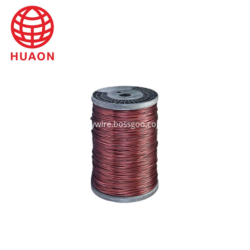
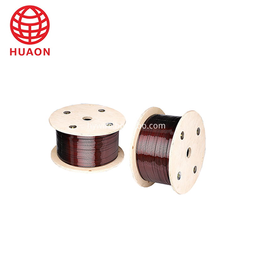
Enameled Aluminium Wire :Aluminium Wire coated with painting
widely used in transformer of microwave oven, three-phase power transformer, rectifier, degaussing coil of large screen color TV set, kitchen motors, magnetic mineral separating equipment, spare parts for automobile, wire and cable, etc.


-
Raw Material:Copper Rod or Aluminium
-
Drawing Rolling :Convert 12.5 mm or 8 mm size of copper rod to size of clients' requirement.
-
Annealing:Heat resistance
-
Japanning: Painting the copper conductor.
-
Finished Products :Copper or aluminum wire
-
Detection:check the quality of finished products through the machine.
-
Packing :PT25/60/90/200 or others
-
Shipping :Container
Enameled Aluminium Wire
Enameled Aluminium Wire,Transformer Enameled Aluminum Wire,Polyester Enameled Al Round Wire,Aluminum Wire Winding Magnetic
HENAN HUAYANG COPPER GROUP CO.,LTD , https://www.huaonwire.com

