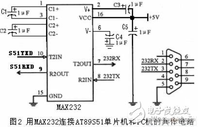
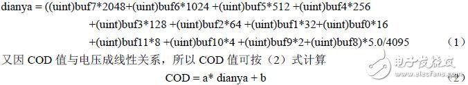
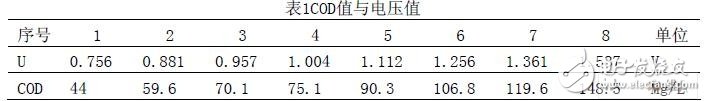
introduction: In the industrial wastewater treatment process, it is often necessary to monitor the COD value of the sewage, and the data monitored by the on-site monitoring instrument is output through various analog signals, which must be converted into digital signals by the A/D converter before being sent. Into the host computer or an external data collector. Based on this, this paper gives the software and hardware design based on A/D converter TLC2543, and combines the least squares method to correct the output data, which meets the requirements of the environmental protection part for the accuracy of organic pollutant monitoring data. 1 system hardware design introduction As shown in Figure 1, the system circuit diagram, A / D converter uses TLC2543, it is a 12-bit serial analog-to-digital converter, using the switching capacitor successive approximation technology to complete the A / D conversion process, because it is a serial input structure, can Save 51 series of single-chip I / O resources; and the price is moderate, the resolution is higher, so it has a wide range of applications in instrumentation. Its characteristics are as follows: A / D converter has 12-bit resolution; conversion time is 10us in the operating temperature range; there are 11 analog input channels; 3 built-in self-test mode [1]; end of conversion (EOC) Output; with single, bipolar output; programmable MSB or LSB preamble; output data length can be programmed to 8 bits, 12 bits or 16 bits. The output length used in this system is set to 12 bits. In addition, the TLC2543 is simple to connect to peripheral circuits. It has three control inputs for CS (chip select), input/output clock (I/O CLOCK), and serial data input terminal (DATA INPUT); analog input terminal AIN0. ~ AIN10 (1 to 9 feet, 11 to 12 feet), 11 input signals are gated by the internal multiplexer. For this system, the AIN0 analog input is selected; the system clock is generated on-chip and synchronized by I/O CLOCK. The positive and negative reference voltages (REF+, REF-) are provided externally, usually VCC and ground, and the difference between them determines the input range. In this system, the input analog signal is the analog quantity of 4~20mA current, that is, the conversion input range voltage is 0~5V. The one-chip computer adopts AT89LS51, as shown in Figure 1. AT89LS51 is a low-power, high-performance CMOS 8-bit MCU with 40 pins. It contains 4k Bytes ISP (In-system programmable) and can be repeatedly erased 1000 times of Flash read-only program memory, 128 bytes of random. Access data memory (RAM), 32 external bidirectional input/output (I/O) ports, 5 interrupt priority levels, 2 levels of interrupt nested interrupts, 2 16-bit programmable timing counters, 2 full-duplex strings Line communication port, watchdog (WDT) circuit, on-chip clock oscillator. Fabricated using ATMEL's high-density, non-volatile memory technology, the device is compatible with the standard MCS-51 instruction set and 80C51 pin structure, and integrates a general-purpose 8-bit central processing unit and ISP Flash memory unit. At the same time, the chip also has three kinds of package forms: PDIP, TQFP and PLCC. In this system, the PDIP package is adopted. The input/output (I/O) port adopts the P1 port as shown in Figure 1, and the P1 port is a 8-bit bidirectional I/O port with internal pull-up resistor, P1's output buffer stage can drive (sink or output current) 4 TTL logic gates. Write "1" to the port and pull the port high through the internal pull-up resistor. This can be used as an input port. 1.1 TLC2543 Main Pin Description AIN0 ~ AIN10, the pin is 1~9, 11, 12: analog input. The 11 input signals are gated by the internal multiplexer (this system uses channel AIN0). DATA OUT, pin 16, 16-state serial output of the A/D conversion result. It is in the high impedance state when it is high, and is active when it is low. DATAINPUT, pin 17, serial data input. The analog input channel is selected by a 4-bit serial address input. I/O CLOCK, pin 18, input/output clock side. The I/OCLOCK receives the serial input signal and performs the following four functions: (1) on the first 8 rising edges of the I/O CLOCK, 8-bit input data is stored in the input data register; (2) at the 4th of the I/OCLOCK On the falling edge, the gated analog input voltage begins to charge the capacitor until the last falling edge of I/OCLOCK; (3) the remaining 11 bits of the previous conversion data are output to the DATAOUT terminal, falling at I/OCLOCK The data changes along the edge; (4) The last falling edge of I/OCLOCK transfers the converted control signal to the internal status control bit. EOC, pin 19, end of conversion. After the last I/OCLOCK falling edge, EOC goes from high to low and remains until the conversion is complete and the data is ready for transmission. The EOC pin changes from high to low on the falling edge of the 12th clock. It marks TLC2543 to start A/D conversion of the analog sample of this sampling. After the conversion is completed, EOC goes high and the flag conversion ends. 1.2 Serial port output circuit introduction As shown in Figure 2, it is the specific circuit diagram of MAX232 chip and single-chip AT89LS51 and PC. The external components are connected according to the standard external components of MAX232. The connection circuit is simple and stable. The connection of serial port pins is also in accordance with the standard industry. Access, where the second pin is the access data, the third pin is the transmit data, the fifth pin is grounded, and the other pins are floating. 2 AD conversion process and implementation As shown in Figure 1, after power-on, chip select CS is high, I/O CLOCK, DATA IN PUT are disabled, DATA OUT is high impedance, and EOC is high. Make CS low, I/O CLOCK, DATA IN PUT enabled, and DATA OUT out of high impedance. Twelve clock signals are sequentially added from the I/O CLOCK terminal. As the clock signal is added, the control word is sent from the DATA INPUT bit by bit to the TLC2543 (high bit first) at the rising edge of the clock signal. The A/D data of one cycle conversion, that is, the data in the output data register is shifted bit by bit from DATA OUT. After the TLC2543 receives the 4th clock signal, the channel number AIN0 is also received. Therefore, at this time, the TLC2543 starts sampling the analog quantity of the selected channel and keeps it to the falling edge of the 12th clock. On the falling edge of the 12th clock, EOC goes low, and A/D conversion is started for the analog quantity of this sampling. The conversion time takes about 10μs, and the EOC becomes high after the conversion. The converted data is in the output data register. One duty cycle output. A new work cycle can then be carried out. 3 Principle and implementation of least squares method The least squares method is based on the principle of stochastic statistics. The test sample value is taken as a random variable, and the sum of the squares of the distances from the obtained line is the smallest [2]. It is directly used in the system. When there is a set of (two-dimensional) experimental data of different sizes, they have an approximately linear relationship, and when an expression that needs to find a linear relationship between them is drawn, first draw In the two-dimensional coordinate system, the points with the test data as coordinates are drawn in the coordinate system, and the principle of least squares can be used to draw a straight line based on the experimental data, so that the sum of the squares of the distance from the straight line to all points is the smallest. Then, the equation of this line can best reflect the linear relationship of the experimental data. How to draw this line and find the equation and slope of the line can be achieved by using excel data processing tools or other linear fitting calculation software. In the above A/D conversion program, buf0~buf7 is the upper 8 bits of the converted data, and buf8~buf11 is the lower 4 bits of the converted data. Since the input range of the analog quantity is 4~20mA, the access impedance resistance is 250Ω, so the range of the voltage after conversion is 1~5V, and the analog quantity 4~20mA is linear with the COD value measured by the measuring instrument, that is, It has a linear relationship with the 1~5V voltage after conversion. Therefore, the slope coefficient a and the constant b of the linear relationship can be obtained by the least squares method. Finally, the COD value is obtained, and the COD value is sent to the PC or other data collector through the serial port. The converted voltage algorithm and COD value algorithm are as follows: Since the 12-bit binary number corresponding to 5V is 111111111111 (that is, the full-scale number 4095), the 5V voltage is divided into 4095 points, each of which is 5/4095, between 1~5V and 0~4095. It is one-to-one correspondence, so the converted voltage can be calculated according to formula (1): The slope a and the constant b in the equation (2) are obtained by the least squares method. As shown in Table 1 below, the COD value and the A/D conversion voltage value monitored by the organic pollution monitoring instrument (model OPM-410A) are linear. In Table 1: U is the voltage value measured after A/D conversion; COD is the COD value monitored by the organic pollution monitoring instrument of model OPM-410A. According to the principle of least squares method, the values ​​of the slope a and the constant b can be found to be 125.3 and (-50.6), respectively, so (2) is: COD=125.3*dianya – 50.6 (unit: mg/L) 4 actual test results The following is a comparison of the COD data monitored by the organic contamination monitor model OPM-410A with the COD data collected by the system. In Table 1, COD1 refers to the COD data value monitored by the model OPM-410A organic pollution monitor; COD2 is the data value collected by the embedded system; error = COD2-COD1; Conclusion: The analog data acquisition system based on high-precision 12-bit serial A/D converter TLC2543 has good flexibility and practicability. TLC2543 can make the circuit simple, improve performance and reduce cost. At the same time, the system adopts the minimum two. The multiplication method linearly sums the voltage value and the COD value so that the collected COD value is closer to the COD value monitored by the organic pollution monitor. After the actual measurement, the system is stable and reliable, and the accuracy of the collected data meets the requirements of the environmental protection part for the accuracy of the organic pollution monitoring instrument. The author of this paper innovates: This paper uses the least squares method to linearly fit the voltage value and the COD value, so that the collected data is closer to the true value, and meets the requirements of the environmental protection department for the accuracy of the organic pollutant monitoring instrument within a certain range. In addition, the system based on the serial 12-bit A/D converter TLC2543 analog data acquisition system has good flexibility and practicability, can achieve a variety of power, non-power, such as voltage, current, temperature, pressure, humidity, etc. Accuracy acquisition and processing. Rubber cable is also rubber sheathed cable. As its name implies, it is a wire and cable with various rubbers or thermosetting elastomers with equivalent performance as the insulation and sheath foundation. Rubber Cable,Rubber Welding Cable,Outdoor Copper Wire Rubber Cable,Flexible Rubber Sheathed Cable Ruitian Cable CO.,LTD. , https://www.hbruitiancable.com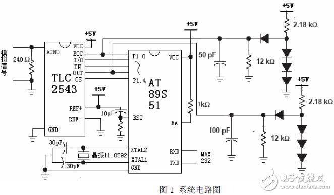
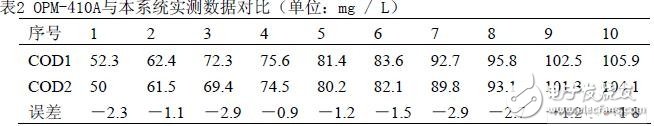
The data in Table 2 is only a part of the random acquisition of the system in the actual test process. It can be seen from the table that the data collected by the system is lower than the data collected by the monitoring instrument, and the error is not less than -3mg/L. It can meet the requirements of organic pollution monitoring in the environmental protection part and achieve the expected results.
Because of its unique flexibility, rubber sheathed cables are very suitable for use in indoor and outdoor environments, including wet and even water conditions. They are usually used on mobile electrical equipment. They are suitable for electrical and pneumatic connection or wiring with AC rated voltage of 300V/500V and 450V/750V below.
Rubber sheathed cables are used by products in many fields due to their unique mechanical and physical properties, so they are classified into many categories, such as mobile universal rubber sheathed cables, electric welding machines, electric power, marine, mining, wind energy, nuclear energy, etc., among which mobile universal rubber sheathed cables and mining cables are widely used.
Advantages
1. Good water resistance, less air permeability.
2. It can be mixed with other rubber or plastics to improve the performance of rubber.
3. Good heat resistance. The heat resistance of rubber is better than that of natural rubber and styrene butadiene rubber.
4. The physical and mechanical properties are average. The mechanical properties of rubber without reinforcing agent are poor.
5. It has excellent oil resistance and solvent resistance. The higher the content of acrylonitrile, the better the oil resistance.