1 Introduction This article refers to the address: http:// 3.2 qt/embedded transplantation 3.2.2 transplantation on the target board Figure 2 software framework structure 3.3.1 user interface module Figure 3 Human machine interface operation diagram 3.3.2 Data Processing Module Figure 4 software flow chart The data acquisition is completed by interrupt acquisition in the driver design of the ad module. The main code of the ad driver function is as follows: (null, device_name, devfs_fl_auto_devnum, 0, 0, s_ifchr|s_irusr|s_iwusr, &s3c2410_fops, null). //Wait for the queue. When the data arrives, the process wakes up and returns the data to the caller. Adcdev.channel=0; Adcdev.prescale= 0xff; //ad setting, which means sampling channel 0. Start_adc_ain(adcdev.channel, adcdev.prescale); Interruptible_sleep_on(&adcdev.wait); Copy_to_user (buffer, (char*)&ret, sizeof(ret)). Table 1 Tools and environment variables required for migration on the host 4 Summary Led Flood Light is a good
choice for outdoor lighting whether for industrial or commercial lighting, such
as factories, construction sites, parking lots, stadiums, shopping malls, etc.
You can even put a low-power floodlight outside your home. Led Flood Light,Flood Light,Led Flood Light Outdoor,Led Flood Light 200W ZHONGSHAN G-LIGHTS LIGHTING CO., LTD. , https://www.glightsled.com
The detection of state parameters in the production process of the battery is the key to ensuring the quality of the battery. At present, however, the state detection of domestic batteries mainly relies on battery voltage inspection instrument, battery conductance tester and internal resistance capacity tester. These instruments can only realize a single detection battery state, and the operation flexibility is limited, data storage, Both transmission and real-time analysis require additional PC assistance, which is not well suited to many of today's demanding industrial field control applications. In order to make the battery performance parameter measurement on the battery production line more flexible, this paper proposes a qt/embedded portable battery state detection system, which realizes multi-channel data acquisition of the battery. The control software interface is friendly and the detection instrument is light and convenient.
2 overall system design and implementation
The detection system consists of data acquisition part, a/d conversion, arm microcontroller and data storage. The overall architecture design is shown in Figure 1. Among them, the data acquisition part mainly completes the collection of battery performance parameters, and the a/d conversion part mainly completes the analog/digital conversion of the collected signals. The arm microcontroller is a key part of the whole system, and is mainly responsible for the connection with qt/embedded. Accept the command information of the third-party user and handle it accordingly. The data storage part is mainly responsible for storing the processed data in the usb device to provide a basis for future data analysis.
3 control software design
3.1 Introduction to qt/embedded
Qt/embedded is a complete and self-contained gui and linux-based embedded platform tool that is the version of qt on the embedded platform. It interacts directly with linux i/o and framebuffer through qt api, has high operating efficiency, and adopts object-oriented programming as a whole, with good architecture and programming mode. Qt/embedded can directly build control software for embedded devices, providing a good human-computer interaction interface for portable devices, making the operation of the device more flexible. 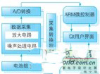
Figure 1 Composition of the measurement system
In this paper, the host-target board migration method is adopted. After debugging on the host machine, the program passed through the debugging is transplanted to the target board.
3.2.1 Migration on the host machine
Qt/embedded writes directly to the framebuffer. On the host machine, the frame buffer is simulated by qvfb (vituralframe buffer). The tools and environment variables required for the migration on the host are shown in Table 1. The setting of environment variables can be directly declared with export. When configuring qt-embedded-3.3.2, /configure–qconfig–qvfb–depths4,8,16,32 is the specified qt/embedded development package to generate virtual buffer frame tool qvfb. .
Apply the qt/embeded program to the arm development board and configure the linux-arm-g++ configuration option [6] during configure configuration. Finally, the cross-compiled application is burned to the /opt directory of the root file system of the development board.
3.3 The framework of the application
The battery state detection control software based on qt/embedded includes the following four main modules, as shown in Figure 2. 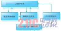
The user interface is shown in Figure 3. It mainly includes staff information (part 31), battery information (part 32), and data to be displayed (part 33) (ideal data, upper and lower limits of data, actual test data, and current The state of the battery) and the data storage (part of Figure 34) are composed of several parts. Among them, before the inspector works, it is necessary to manually input the employee information and the device information to facilitate the classification of the data, and finally store the data together. 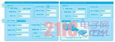
The basic structure of the acquisition data processing module is shown in Figure 4. After the system is started, the initialization of the arm microprocessor chip is first performed. After the initialization is completed, the system starts the qt host computer software, and then the entire program enters the listening state, continuously detecting whether there is a control command event trigger, and once triggered, a/d is performed. Conversion, the information collected by the data acquisition module is digital/analog converted, and finally the processed data is sent to the display module for display. 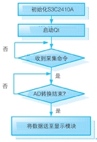
(1) Device initialization, registration of the drive device. In order to prevent the conflict of device numbers, the device registration here is to automatically assign the device number.
Devfs_handle=devfs_register
(2) open function, used to set the ad channel, and scale factor initialization.
Init_waitqueue_head (&adcdev.wait);
(3) read function, one of the key functions, in this function you need to configure the control register of the ad device, and start the conversion. Use the copy_to_user function to pass data from the kernel to the user space. The main function of the function is as follows:
(4) Finally, write all the function functions into file_operations. 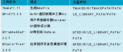
Data collection is an essential part of the research and design of various detection systems. Based on the s3c2410a microcontroller, this system uses the graphical programming language qt to design a visual and friendly control interface, which can significantly improve the display effect of the human-machine interface. The system has high stability and reliability, and is especially suitable for portable detection devices. Therefore, the system has broad market prospects.
Safety Flood Light. It will bring you a bright night under the lighting of our
durable, energy efficient and safety floodlight.
Power of flood light could be various, from 3watt to 1000watt. Good design with
qualified quality makes your project work perfectly.