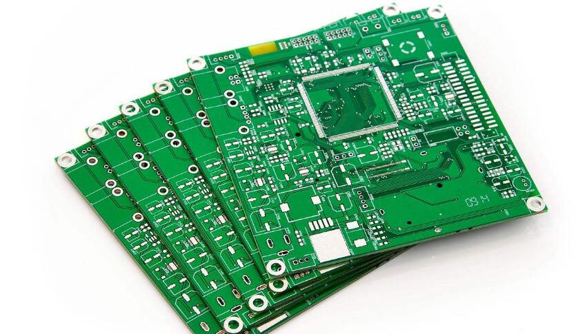
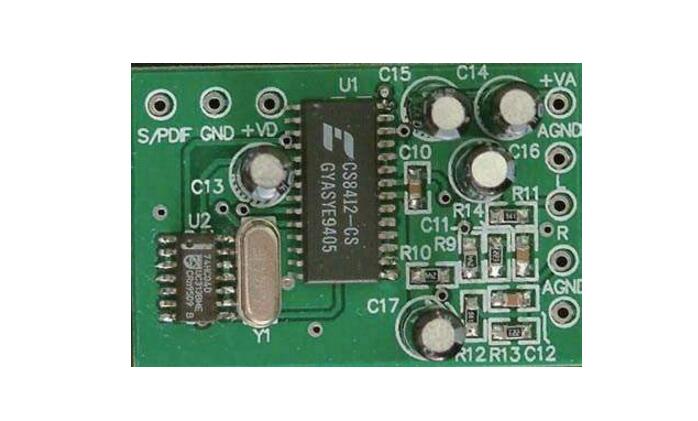
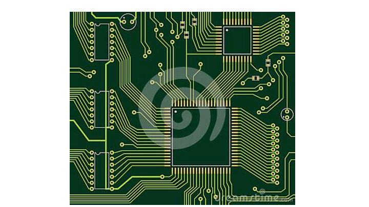
At present, the welding of electronic components mainly uses soldering technology. The soldering technology adopts a tin-based tin alloy material as the solder. The solder melts at a certain temperature, and the metal weldment and the tin atoms attract, diffuse and combine with each other to form an infiltrated bonding layer. It seems that the copper and platinum components of the printed circuit board and the component leads are very smooth. Actually, there are many tiny concave and convex gaps on the surface. The molten solder is spread along the surface of the weldment by capillary suction to form solder and solder. The infiltration of the parts firmly bonds the components to the printed board and has good electrical conductivity. The conditions for soldering are: the surface of the weldment should be clean, grease, rust can affect the weld; the metal that can be wetted by the tin solder has solderability, and the material that easily forms an oxide film on the surface of the brass, etc., can be assisted by Flux, after the surface of the weldment is first tin-plated and infiltrated, then re-welding; with proper heating temperature, the solder material has a certain degree of fluidity before the purpose of welding can be achieved, but the temperature can not be too high. When it is high, an oxide film is easily formed to affect the quality of welding. The main tool for manual welding is electric iron. There are many kinds of soldering irons, such as direct thermal type, induction type, energy storage type, and temperature control type. There are 15W, 2OW, 35W, ...300W electric power, which are mainly determined by the size of the weldment. The welding of general components should be done with a 2OW internal soldering iron. When soldering integrated circuits and vulnerable components, it can use energy-storage soldering irons. When soldering large solders, 150W~300W high power external soldering irons can be used. The temperature of the tip of a small power soldering iron is generally between 300~400°C. Iron heads are generally made of copper material. In order to protect the rust from oxidation under the high temperature conditions of soldering, the soldering iron head is often plated and some iron tips are made of alloy materials that are not easily oxidized. The new tip should be tin plated before it is officially welded. The method is to polish the iron head with fine yarn paper, then dip in the pine perfume, and dip the solder on the hard object (such as a wood board) repeatedly to make all the tin of the soldering iron head tin-plated. If it is used for a long time, when the iron tip has been oxidized, use a small file to lightly remove the surface oxide layer. After exposing the bright copper, use the same method as tin plating with a new tip. When using only a soldering iron, the temperature of the soldering iron tip can be adjusted by varying the depth of the soldering iron core. The longer the iron head is drawn from the iron core, the lower the temperature of the iron head, and the higher the temperature. It is also possible to use the size and shape of the replacement tip to adjust the temperature of the tip. The finer the tip, the higher the temperature; the thicker the tip, the lower the relative temperature. Depending on the type of component being soldered, a properly shaped tip can be selected. The tip of the iron tip has a conical shape, an oblique oval shape, and a chisel shape. Small solder joints may be conical, and larger solder joints may be chiseled or cylindrical. There is also a soldering soldering iron, which is composed of a tin-absorbing mechanism added to the direct-heating soldering iron. This soldering iron is used when the components are desoldered in the circuit. At present, the mainstream circuit board assembly technology in the SMT industry should not be "reflow", and there are of course other circuit board soldering methods. This kind of full board reflow soldering can be divided into single-panel reflow soldering and The double-sided reflow and single-sided reflow boards are rarely used now, because the double-sided reflow can save the space of the circuit board, which means that the production can be made smaller, so most of the boards on the market are seen. It belongs to double-sided reflow process. Because the "double-sided reflow process" requires two reflows, there will be some process limitations. The most common problem is that when the board reaches the second reflow furnace, the parts on the first side will be Falling due to the relationship of gravity, especially when the board flows to the high temperature of the reflow area of ​​the furnace, this article will explain the precautions for parts placement in the double-sided reflow process: Generally speaking, the relatively small parts are recommended to be placed on the first side of the reflow furnace, because the first side of the reflow furnace when the PCB deformation will be smaller, the solder paste printing accuracy will be higher, so it is more Put smaller parts. Second, the smaller parts do not have the risk of dropping when they pass through the oven for the second time. Because the part of the first side will be placed on the bottom surface of the circuit board directly downwards when playing the second side, when the board enters the high temperature of the reflow area, it will not drop from the board due to the excessive weight. Thirdly, the parts on the first panel must go through two reflow furnaces, so the temperature must be able to withstand the temperature of the two reflows. The common resistors and capacitors are usually required to have at least three reflow temperatures. This is to Conforms to the requirements that some boards may require to retake the reflow oven due to maintenance. Which SMD parts should be placed on the second side of the reflow oven? This should be the focus. Large or heavier components should be placed on the second surface to avoid the risk of parts falling back into the oven when passing through the furnace. The LGA and BGA parts should be placed on the second side as much as possible to avoid unnecessary re-melting of the tin when the second pass is performed, so as to reduce the chance of empty/false welding. If there are thin legs and smaller BGA parts do not rule out the placement of the first side of the reflow oven. It is always controversial that the BGA has been placed on the first side or on the second side. Although placing the second side can avoid the risk of re-melting the tin, the PCB will generally be deformed more severely when the second side is returned to the oven. Instead, it will affect the quality of eating tin, so the working bear will say that the BGA can not consider the thin feet can be considered first. But think in reverse, if the PCB is seriously deformed, as long as the fine parts are placed on the second side, the patch must be a big problem, because the solder paste printing position and the solder paste volume will become inaccurate, so the focus should be Think of ways to avoid PCB distortion instead of thinking about putting BGA on the first side because of distortion, isn't it? Parts that cannot withstand too many high temperatures should be placed on the second side of the reflow oven. This is to prevent parts from being damaged by too many high temperatures. Parts of PIH/PIP must also be placed on the second side of the furnace, unless the length of the welding leg does not exceed the thickness of the plate, otherwise its feet protruding from the surface of the PCB will interfere with the steel plate on the second side, which will make the second side Paste-printed steel plates cannot be attached to the PCB to cause solder paste printing abnormalities. Some components will use soldering inside. For example, there is a LED cable connector. It must pay attention to whether the temperature resistance of this part can be twice the reflow oven. If not, it must be placed on the second side. Only the parts placed on the second side of the patch patch over-reflow oven, it means that the circuit board has passed a high temperature baptism of the soldering furnace, this time the circuit board has been somewhat warped and deformed, that is to say that tin The amount of paste printed and the location of printing will become more difficult to control, so it will easily lead to air welding or short-circuit problems. Therefore, on the second side of the furnace parts, it is recommended not to place 0201 and fine feet (finepitch) ) Parts, BGA should also try to choose a larger diameter solder ball. In addition, in mass production, electronic components are soldered and assembled on circuit boards. There are actually many kinds of process methods. However, each process is actually decided at the beginning of the circuit board design, because its circuit board The placement of the parts will directly affect the assembly order and quality of the assembly, and the wiring will indirectly affect. Double-sided circuit board In order to ensure that the double-sided circuit has a reliable conductive effect, the connection hole (ie, the metalization process through-hole portion) of the double-sided board should be firstly soldered with a wire or the like, and the protruding portion of the connection wire tip should be cut out to avoid damage. Injured operator's hand, this is the board's connection preparation. Double-sided circuit board welding method: 1. For devices that require shaping, process processing shall be performed according to the requirements of the process drawings; 2. After the shaping, the model face of the diode should face upwards, and there should be no inconsistency between the lengths of the two pins. 3. When inserting a device with polarity requirements, it must be noted that its polarity must not be reversed. The roll-integrated block component, after insertion, must not be tilted either vertically or horizontally. 4, the use of soldering iron welding power between 25 ~ 40W, the temperature of the iron head should be controlled at about 242 °C, the temperature is too high head easy to "die", the temperature can not melt the solder, the welding time is controlled at 3 ~4 seconds. 5, the general welding is generally in accordance with the device from low to high, from the inside to the outside of the welding principle to operate, welding time to master, too long time will scald the device, will also burn the copper on the copper clad lines. 6, because it is double-sided welding, it should also be a circuit board to place the circuit board and the like, the purpose is not to depress the following devices. 7, after the completion of the circuit board welding should be carried out a full check-in seat type inspection, check the leakage plug leakage welding place, confirmed after the circuit board extra device pins and the like trim, and then into the next process. 8, in the specific operation, should also strictly follow the relevant process standards to operate to ensure the quality of welding products. When the double-sided circuit board that has been soldered to others is repaired, it may be difficult to repair it due to dirty, chaotic, and possibly defective soldering, broken wires, and poor contact. Xiao Bian's experience is: 1. Observation: According to the drawings or prototypes, a general understanding of physical lines and trends. 2. Dismantling: Remove the welded components, plug sockets and flying wires. 3. Cleaning: Clean the rosin and welding oil on the surface of the circuit board with anhydrous alcohol. When cleaning, such as using a soldering iron with heating is faster and better. 4. Route: Check the direction of the route carefully with reference to the observation, and use the drawing method to assist the annotation when no picture is available. 5, welding: According to the clear line welding. When disconnecting wires, they should be arranged on the back; 6, check: According to the results of the analysis of drawings or prototypes and the front line. Check whether the welding is correct and reliable, and whether the process meets the requirements; 7, power test machine. Gaming Earbuds With Mic,Metal Body Earphones,Sport Metal Headphone,Wired Metal Earphone Guangzhou YISON Electron Technology Co., Limited , https://www.yisonearphone.com


Double sided board re-soldering tips
Welding principle and welding tool welding principle: