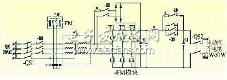
The core value of the smart grid is to improve energy efficiency, use various high-tech methods to improve the operation and management level of each link of power generation, transmission, distribution, and power consumption, save resources and protect the environment; the smart grid is more suitable for multiple energy units for power generation, distribution, The need for electricity usage is more suitable for the market-oriented power trading needs, and is more suitable for customers' independent choices. Electric vehicle to grid ( V2G ) technology is the two-way interaction and exchange of electric vehicle energy with the power grid in a controlled state. It is an important part of "smart grid technology" and applies V2G and smart grid technology. Therefore, the charging and discharging of electric vehicle batteries are deployed in a unified manner. According to the established charging and discharging strategy, on the premise of meeting the driving needs of electric vehicle users, the surplus electric energy is controlled and fed back to the power grid in two directions. 1 V2G system information flow V2G embodies energy bidirectional, real-time, controllable, and flows between the vehicle and the grid.The charge and discharge control device has both interaction with the grid and interaction with the vehicle.The interaction content includes energy conversion information, customer demand information, Power grid status, vehicle information, metering and billing information, etc. Therefore, V2G is a high-end comprehensive application of many technologies such as power electronics, communication, dispatching and metering, and demand-side management. Figure 1 shows the V2G system information map SM: Smart electricity meter, two-way measurement, local information storage, RS485 communication with EV2PCS, and transmission of power information to UT through EV2PCS; EV2PCS: Two-way intelligent charge and discharge device, composed of a low-voltage controller and a local management machine, used to achieve two-way energy interaction between the vehicle and the power grid, is a key device of the V2G system; UT: Human-computer interactive terminal, which is the interface between electric vehicle users and the grid, from which users obtain information on electricity consumption and electricity charges; BMS: battery management system, used for the collection and transmission of vehicle battery data, monitoring of battery operating status, communication with EV2PCS via CAN bus, and transmission of vehicle information to the background through EV2PCS; EMS: background management system, communicate with the grid dispatching system on the upper side, obtain grid load information and execute grid dispatching instructions, communicate with the EV2PCS on the lower side, obtain vehicle status information, and allocate and dispatch the power generation network dispatching instructions. 2 V2G system components 2. 1 two-way intelligent charge and discharge device As a key power component in V2G technology, the two-way intelligent control device is used to realize the two-way flow of energy between the power grid and electric vehicles.It can work in charging mode and V2G mode: if you select the charging working mode, you only charge the vehicle, not The vehicle battery energy is fed back to the grid; if the V2G operating mode is selected, the device will connect the vehicle to charge and discharge according to the upper and lower SOC thresholds of the vehicle selected by the user on the human-machine interactive terminal, or the default upper and lower SOC thresholds of the device The real-time capacity, controlled time and other information are provided to the background management system. The background management system issues a charge and discharge control command. The device performs charge and discharge operations according to the current SOC of the vehicle battery to achieve two-way flow of energy. Figure 2 shows the main loop topology of the two-way intelligent control device Its topological characteristics are as follows: (1) The three-phase full-bridge two-way PWM conversion is used to charge and discharge the battery; (2) The grid AC and the battery side of the electric vehicle are electrically isolated by an isolation transformer (3) Simultaneous isolation transformer can perform voltage matching between AC and DC; (4) The AC side and DC side are equipped with overload and overcurrent circuit breakers; (5) The AC and DC sides are equipped with a pre-charging circuit, and the starting method is flexible; (6) Adopt one-level converter, with simple topology and high reliability. 2. 2 Human-computer interactive terminal The structure of the human-computer interactive terminal system is shown in Figure 3, which is mainly composed of an embedded controller, a touch screen, a radio frequency card reader, a CAN communication card, a remote monitoring and communication expansion card, and a micro printer. The main functions are: interface display, identification, EV2PCS control mode, ticket printing, data management and query, personalized parameter settings, language switching, and user operation assistance and abnormal information prompts. Figure 3 shows the structure diagram of the human-computer interactive terminal system Fiber optic adapters are typically used to connect two fiber optic cables together. They come in versions to connect single fibers together (simplex), two fibers together (duplex), or sometimes four fibers together (quad). Adapters are designed for multimode or single-mode cables. The single-mode adapters provide more precise alignment of the tips of the connectors and can be used to connect multimode cables. The reverse is not suggested as this might cause misalignment of the small single-mode fibers and loss of signal strength (attenuation).
Optical attenuators can take a number of different forms and are typically classified as fixed or variable attenuators. What's more, they can be classified as LC, SC, ST, FC, MU, etc. according to the different types of connectors.
Sijee provides different types of Optical Fiber Attenuator, Fiber Optic Attenuator, Fiber Optic Fixed Attenuator, FC Fiber Attenuator.
Fiber Optic Attenuator Optical Fiber Attenuator,Fiber Optic Attenuator,Fiber Optic Fixed Attenuator,FC Fiber Attenuator Sijee Optical Communication Technology Co.,Ltd , https://www.sijee-optical.com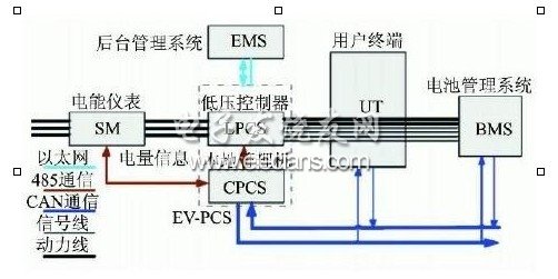

Optical attenuators are commonly used in fiber-optic communications, either to test power level margins by temporarily adding a calibrated amount of signal loss, or installed permanently to properly match transmitter and receiver levels. Sharp bends stress optic fibers and can cause losses. If a received signal is too strong a temporary fix is to wrap the cable around a pencil until the desired level of attenuation is achieved. However, such arrangements are unreliable, since the stressed fiber tends to break over time.
Types: