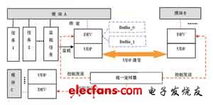
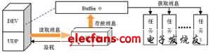
The idea of ​​modularization in software design has become increasingly common. The modular design can make the program structure clear, easy to maintain, and more efficient to develop. Large-scale software is usually composed of multiple functional modules, and the functional realization of the modules is supported by multiple threads. Operating systems such as windows and Linux can manage the communication between threads themselves without much concern about the underlying layer. VxWorks is a multi-task system, and tasks are the most basic execution unit of the system. The communication between functional modules is also the communication between tasks. VxWorks' management of communication between tasks is far from perfect in windows. When the number of modules is large and the communication service is large, the inter-task communication mechanism provided by VxWorks cannot meet the requirements of real-time and resource utilization. This paper proposes a communication model between tasks. The UDP method used for network communication is introduced into the communication between tasks, which makes the communication more flexible and easy to manage, and improves the performance of the entire system. Introduction to multi-task real-time operating system VxWorks VxWorks operating system is an embedded real-time operating system (RTOS), is a key component of the embedded development environment, has the characteristics of high reliability, real-time performance, and scalability. VxWorks provides programmers with efficient real-time task scheduling, interrupt management, real-time system resources, and communication between tasks. Application programmers can focus on the application itself without having to care about the management of system resources. VxWorks can support up to 256 tasks, and supports resource sharing methods such as binary semaphores, mutually exclusive semaphores, and message mailboxes. The efficient and real-time multitasking kernel allows VxWorks to provide similar API interfaces to multiple series of MPUs, MCUs, and DSPs at the same time. Its good portability requires only 1% to 5% of code modification on cross-processor platforms. Good sustainable development ability, high-performance kernel and friendly user development environment make VxWorks occupy a place in the field of embedded real-time operating system. It is widely used in the fields of communication, military, aviation, aerospace and other high-precision technologies and real-time requirements with good reliability and excellent real-time performance, such as satellite communications, military exercises, ballistic guidance, aircraft navigation Wait. Problems with traditional communication methods between modules Most embedded operating systems are used in occasions with high real-time requirements. Due to the limitation of volume and cost, the resources and running speed of embedded systems cannot be compared with PCs. Therefore, the efficiency of applications developed on such systems and reducing resource consumption are very important. VxWorks is a multi-tasking operating system. The traditional inter-task communication model has the following types: shared memory, semaphore, and message queue. These methods have their shortcomings. The shared memory mode uses global variables or caches. For large and complex programs, multiple tasks reading and writing to a variable at the same time will cause conflicts or overflow from the slow-down zone. Although the semaphore communication model can play a mutually exclusive role, when multiple tasks communicate with a certain task at the same time, competition for semaphores will occur, causing queues at the communication initiator and reducing the efficiency of the system. The message queue can avoid the queuing problem caused by the semaphore through the asynchronous message delivery model, but when the number of tasks is too large, the number of queues required is too large, which will consume a lot of system resources. The large number of modules and the large number of communications cause task queuing and resource consumption that will affect the real-time performance and system performance of VxWorks. The communication model described below has certain advantages in overcoming the above problems. Principle and performance analysis of communication model The whole communication model is composed of four parts: business module, UDP socket, virtual device controller (DEV) and unified timer. The modules use UDP-based communication for information interaction. The UDP socket is bound to the business module through a virtual device controller (DEV) concept, and a loosely coupled relationship exists between the two. Each module has its own DEV, which is responsible for managing UDP sockets to interact with other modules. The unified timer is responsible for coordinating and controlling the timing of messages sent by the service module. The unified timer and DEV combine to complete the communication between modules. UDP was originally a connection-free network communication method, and its introduction into a program as a means of communication needed to examine its reliability. Although UDP communication is connectionless, it may cause packet loss when the network is not good, but because the program is running on a host, the interaction between the various modules in the program is also limited to the local machine, not through Network, so the probability of UDP packet loss is very small, and communication reliability can be fully guaranteed. The schematic diagram of the communication model is as follows: Figure 1 Schematic diagram of the communication model 1 The concept of virtual device controller (DEV) The virtual device controller (DEV) is essentially a data structure, and each module obtains its own DEV by declaring such a data structure. The DEV records information about the UDP socket, module number or module name. DEV also includes two ring buffers for data interaction with the module. The UDP socket is closely integrated with the DEV, but it is not directly connected with the module. That is to say, a UDP does not belong to a certain module, and they are loosely coupled. The introduction of the DEV concept abstracted the UDP socket as a virtual device for the module to use. The communication function and the business function of the module are separated from each other, more independent, and the efficiency is improved. The module and the UDP socket can also be flexibly configured and released through the DEV. The structure of DEV is as follows: Struct DEV { int Module_ID; // Record the module number; int SocketKind; // Record socket type; int socket_ID; // Record socket handle struct RINGBUF_t m_Buf [2]; // Two ring buffers: [0] for input [1] for output } During software initialization, you can apply for several idle DEV devices. When a service module starts, you can apply for an idle DEV for your own use. Fill the Module_ID in the DEV structure variable with the number of the business module to complete the binding of the module and the DEV. Apply for another UDP socket, store the socket handle in the socket_ID variable of the DEV structure to complete the combination of UDP and DEV, so that the business module establishes contact with UDP through DEV, and the module can control and use UDP through DEV Communication. When the module no longer needs to use UDP, or the UDP socket fails, you can set the Module_ID and socket_ID in the DEV it owns to 0, cancel the connection between the module and the DEV, and complete the release of UDP. When the module needs to use UDP again, it can reapply for DEV and UDP. This way of sending and coupling makes the normal operation of the module not affected by UDP and improves the reliability of the program. 2 The role of the unified timer The unified timer is responsible for coordinating all UDP transmissions. After the program is initialized, the unified timer is started, and a specific action will be performed as soon as the timer expires. It will poll all DEVs and send the contents of the DEV sending buffer through UDP. 3 Realization of communication ①Send UDP message When a task of module A needs to communicate with other modules, it will package the information and send it to other modules via UDP. The task (thread) of module A puts the message packet that needs to be sent into the DEV's No. 1 cache. The unified timer polls all DEVs every time it reaches a certain time. If there is information waiting to be sent, it passes through the UDP controlled by the DEV The jack sends the message to its destination. ② UDP message reception As shown in Figure 2, each module has a monitoring task (thread) that is responsible for regularly monitoring the UDP port controlled by the DEV corresponding to the module. Once UDP receives a message, the thread is responsible for receiving the received message from the UDP cache Read it out and store it in DEV No. 0 cache. When other work tasks of the module need to obtain the message, they can read and parse the message from the cache No. 0. Figure 2 UDP message reception 4 Performance analysis of the communication model The above communication model adopts a quasi-asynchronous method, each module is synchronized when sending a message, and asynchronous when receiving a message. It can avoid conflicts during multi-module communication, and can save resources, which is superior to the traditional communication model in efficiency. The loosely-coupled mapping relationship enables the flexible combination and release between the module and the communication port, which brings greater freedom to the design of the software structure. ①Efficiency: A timer polling message sending method is adopted to avoid conflicts in task communication. When the module sends UDP messages to other modules, it only needs to pack the message into the sending buffer of the DEV, and the sending of the packet is completed by the unified timer. The module itself does not care about sending data packets. You can do other work after putting the packet in the DEV. In the case of multiple modules communicating with a module at the same time, this method will not appear in the semaphore model queue waiting for the semaphore phenomenon, improve the efficiency of the system, real-time performance is guaranteed. Since the sending of all modules is completed by the timer, the program code is streamlined, and the commonality of the code is enhanced. ②Utilization of resources: Due to the use of UDP, a more flexible communication method, messages are sent only when communication is required between modules, without having to establish multiple message queues between each module. When the number of modules is large, this method is more obvious in terms of resource saving. For example: there are n modules, and it is necessary to establish a pair of message queues between two or two (n-1)! For queues, the program has to maintain a large number of message queues, which consumes a lot of resources. Using the communication model in this paper will save limited system resources and fully adapt to the development of embedded systems. ③ Solution to the problem of message accumulation: In the traditional communication model, the module sends messages without restrictions. As long as there is a message that needs to be sent, the send function is called immediately. If multiple modules send a message to a module at a time, and the module that receives the message has no time to process it, the accumulation of messages will cause the benefit of the buffer. The method of unified timer makes the sending of messages orderly and restricted to a certain extent. The module can process the previously received message during the intermittent period of two polling of a module by the timer twice to make a new message. Well prepared. As long as the timer's timing time is set properly, buffer overflow can be avoided. Implementation of communication model Vxworks is a multi-tasking operating system. The various components of the model can be implemented through tasks. The VxWorks network programming interface and timer are very convenient to use and provide users with an open API. You only need to use socket (), send (), receive (), CreateTImer (), SetTImer () and other functions to operate sockets and timers. In the initialization process of the program, the timer task can be started first, and then a sufficient number of DEVs are generated, and then each module is sequentially started. In the process of starting each module, first apply for an idle DEV, then generate a UDP socket, and establish a mapping relationship between the socket and the DEV. After completing the binding of the module and DEV, start a monitoring task (Moniter_Task) to monitor the UDP port. At this point, the communication model is established. Finally, other work tasks of the startup module start the normal business process. Conclusion This paper proposes an inter-module communication model that is different from traditional communication mechanisms. The introduction of the UDP method for network communication into the inter-module communication in the program avoids the problem of reducing efficiency and excessive resource consumption that may be caused by the traditional method. Through the coupling method of sending and sending, the flexibility of the program is enhanced. In the experiment, this kind of communication model based on UDP virtual device binding has achieved good results, and it has a higher value in the development of embedded systems with higher real-time requirements.
APM model SPS300VAC9000W 3 Phase AC Power Source system is able to provide not only stable DC/AC Output Power,but also 3-phase / 1-phase output.The 3 Phase Ac Power Supply is with high speed DSP+CPLD control, high frequency PWM technology, active PFC design. Reliable ac sources for applications such as electric, lighting, aviation sectors, enterprise`s production test etc.
Some features as below:
9000W Three Phase AC Source System 8100W Three Phase AC Source System,System For Three Phase,Three Phase Power,Three Phase Power Supply APM Technologies (Dongguan) Co., Ltd , https://www.apmpowersupply.com