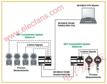
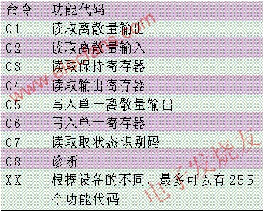
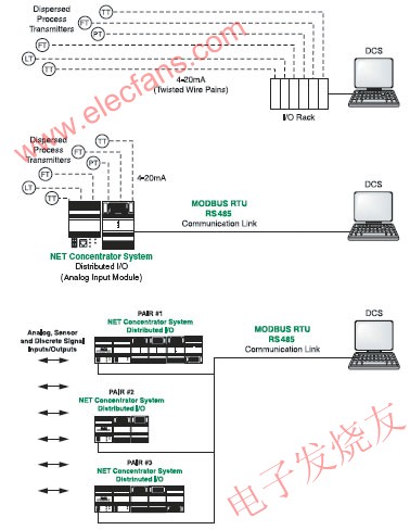
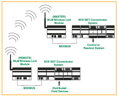
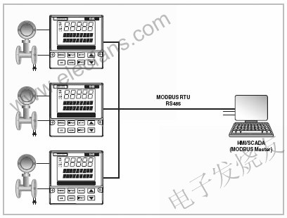
For various reasons, MODBUS is one of the most popular industrial protocols used by everyone today. It is simple, cheap, versatile and easy to use. Another advantage of MODBUS is that it can actually communicate through any transmission medium, including twisted pair, wireless communication, optical fiber, Ethernet, telephone modem, mobile phone and microwave. This means that a MODBUS connection can be easily established in a new or existing factory. In fact, an application that is growing in the field of MODBUS applications is the use of existing twisted pair connections in old factories to provide MODBUS digital communications. In this white paper, we will study how MODBUS works and take a look at some clever ways to use MODBUS in new and old factories. Figure 1: A MODBUS RTU network consisting of a "master station (a PLC or DCS)" and up to 247 "slave" devices. Its network architecture is a multi-branch network connection. Table 1: Function codes What is MODBUS? MODBUS is a communication protocol developed by Modicon (now Schneider Electric) in 1979. Its purpose is to use a twisted pair to communicate with many devices. The original scheme used RS232 interface, but MODBUS is also suitable for RS485 interface in order to obtain a higher communication rate, a longer communication distance and achieve a true multi-branch network structure. MODBUS soon became a de facto standard in the automation industry, and Modicon also released it to the public without any royalties. Today, MODBUS_IDA (www.MODBUS.org), the largest MODBUS user and supplier organization, continues to support MODBUS protocols worldwide. MODBUS is a system with a "master-slave" structure, where the "master device" communicates with one or more "slave devices". The more typical main equipment is generally PLC (programmable logic controller), PC, DCS (distributed control system) or RTU (remote terminal unit). The slave devices of MODBUS-RTU are generally field instrumentation devices. All these field instrumentation devices are connected to the system in a multi-branch network, see Figure 1. When a MODBUS-RTU master device wants to get data from a slave device, the master device sends a message containing the device address, the required data, and a checksum code for error detection. All other devices on the network can see this message, but only the device with the specified address will respond. The slave devices on the MODBUS network cannot initiate communication, they can only react. In other words, they can only speak when others speak to it. Some manufacturers are developing "hybrid" MODBUS devices. Their normal operating mode is similar to MODBUS slave devices, but they have the ability to "write", so sometimes these devices will operate as "pseudo master devices". The three most common versions of MODBUS currently in use are: â– MODBUS ASC II â– MODBUS RTU â– MODBUS / TCP All MODBUS information is transmitted in the same format. The only difference between these three different types of MODBUS versions is: how the information is encoded. In the MODBUS RTU protocol, data is encoded in binary, and each byte of data requires only one byte of traffic. MODBUS RTU is an ideal communication protocol for RS232 networks with a communication speed of 1200 to 115K baud rate or RS485 networks with multi-drop networks. The most common communication rates for MODBUS RTU are 9600 and 19200 baud rates. MODBUS RTU is the most widely used industrialized protocol, so the main part of this white paper will focus on the basic concepts and applications of MODBUS RTU. MODBUS RTU basics In order to communicate with a slave device, the master device will send a message containing the following: â– Device address â– Function code â– Data â– Error checking The device address is a number from 0 to 247. The message sent to address 0 (broadcast message) can be received by all slave devices, but the numbers 1 to 247 are the address of a specific device. There is an exception in this message broadcast. There is a slave device that always reacts to the MODBUS message, so that the master device knows that this message has been received by the slave device. The function code defines the commands that the slave device should execute, such as reading data, receiving data, reporting status, etc. (see Table 1). The function code is a number from 1 to 255. Some function codes also have sub-function codes. The data defines the address in the device memory map for the read function. It includes the data value written to the device memory or other information that needs to be executed according to the requirements of the function code. Error checking is a 16-bit value that describes the cyclic redundancy check (CRC). The Cyclic Redundancy Check Code (CRC) is generated by the master device (by a complex program that includes ORing and shifting the data), and is checked by the receiving device. If the CRC value does not match, the device will request a retransmission. In some systems, data parity is also checked. When the slave device performs the required function, it will return a message to the master device. This returned message contains the address of the slave device, the required function code (so that the master device knows who is responding), the requested data, and an error check value. MODBUS memory map Each MODBUS device has a memory, which stores process variable data. The configuration of MODBUS determines how data is recovered and what type of data can be recovered. However, the MODBUS configuration does not specify how equipment vendors must map these data and which part of the memory must be mapped to these data. The following is a more common example to illustrate how a supplier may theoretically map different types of process variable data. Discrete input and output are 1-bit values, and each such variable has a clear address. Analog inputs (also called "input registers") are stored in 16-bit registers. Just use two of these registers, MODBUS can support IEEE 32-bit floating point format. Holding registers are also 16-bit internal registers and can support floating-point formats. MODBUS configuration defines the data in the register map. Assuming that the equipment supplier complies with the requirements of the MODBUS specification (not all equipment suppliers), then the MODBUS master device can easily obtain all the data complying with the specifications. In many cases, device vendors have announced the memory mapping location (see Table 2), which allows programmers to It is easy to program the communication between the master and slave devices. Table 2: The instructions or operation manuals of most MODBUS compatible devices (such as TMZ temperature transmitters from Moore Industries) publish the addresses of key variables in the memory map. The address of the TMZ temperature transmitter complies with the requirements of the MODBUS specification. Read and write data MODBUS has a maximum of 255 function codes, but 01 (read output volume), 02 (read discrete input), 03 (read holding register), and 04 (read input register) are the most commonly used read function codes. The code is used to collect data from the MODBUS slave device. If the device complies with the requirements of the MODBUS configuration, then setting the master device to read and write data, check the status, obtain diagnostic information, and perform programming tasks for various control and monitoring functions becomes very simple. In most factories, the field instruments are connected to the control system using a separate control room directly connected twisted pair cable (see figure below). When the instrumentation device is connected to a decentralized I / O system (such as the NCS system from Moore Industries) (see middle picture), you can add more field devices, but only need a twisted pair cable You can transfer all data to the MODBUS master station. When multiple NCS systems are connected in a MODBUS network (see the figure below), the connection of the entire plant can be changed from the direct connection of the twisted pair cable control room to the MODBUS connection. Figure 2: Direct control cable vs MODBUS in the control room Figure 3: Peer-to-peer connection mode. In some cases, the control system cannot process MODBUS signals. In this case, a peer-to-peer network solution using dual NCS equipment can be used, and all direct control cables in the control room can be replaced with only one MODBUS cable. The analog output from the second NCS is hard-wired and directly connected to the I / O board of the control system. Connect MODBUS equipment The easiest way to connect field devices to a process control system, PLC or industrial computer system is to simply connect digital and analog I / O to a distributed I / O system with MODBUS communication capabilities . For example, the NCS (Net Concentrator System) system from Moore Industries allows users to remotely connect analog and digital signals, and then connects to a MODBUS master device through twisted pair. Multiple NCS systems can be installed at several different locations throughout the plant, all connected via MODBUS (see Figure 2). This solution is suitable for new factories as well as existing factories. In many existing factories, field instrumentation equipment is usually connected to the DCS or PLC system using multi-core cables, and each device transmits the analog signal through a separate twisted-pair cable. With the NCS system, only one of these cables is needed to transmit the MODBUS signal. This solution is particularly useful if the factory wants to add additional field instrumentation equipment but does not want to install more cables (cable installation costs are usually $ 100 per foot). A set of decentralized I / O system can meet the needs of all existing instrument I / O, or just use it to transmit data from all newly added field instrument equipment. In some cases, the control system cannot handle MODBUS signals. For example, the existing control system may be customized to handle 4 to 20 mA analog I / O and directly wired digital I / O, and it is also very reprogrammed for the existing old system to support MODBUS. difficult. Generally, users do not tend to connect newly added remote signals into the system by laying new cables or buying expensive MODBUS interface cards, because it is very expensive to reprogram the MODBUS interface cards. In this case, a peer-to-peer network solution (peer to peer) can solve the problem well. For example, CCS (Cable Concentrator System) and NCS (Net Concentrator System) systems from Moore Industries both have peer-to-peer network communication capabilities. NCS and CCS systems are very similar to a set of decentralized I / O modules, but have stronger built-in intelligence. In addition, the NCS and CCS systems can be set to a peer-to-peer network mode or a master-slave network (peer to host) mode. Using a set of peer-to-peer network mode NCS system (see Figure 3), two network concentrators are configured; one is installed on site and the other is installed in the control room. The field instrument is connected to the remote NCS. The remote NCS and the NCS in the control room are connected by a twisted pair. Then the output of the control room NCS is connected to the analog I / O board of the existing control system through hard wiring. With this method, the analog signal from the newly added field transmitter can be connected to the control system through the existing analog I / O card in the factory in the state of the original analog signal. This makes the programming and debugging work brought by the newly added signal greatly reduced compared with the newly added digital interface card. This peer-to-peer network solution can also meet the requirements of two-way communication. In this case, both the field side and the control room side of the system can have input and output capabilities. HART with MODBUS Another challenge faced by old-fashioned factories is to find a cheap and convenient way to take advantage of the already installed and "to be installed" HART smart meters. HART means addressable remote sensor high-speed channel. HART is a digital protocol, which was originally designed to enable transmitters to be transmitted over traditional factory-installed copper twisted pairs Digitized data is transmitted at the same time as an analog signal. This enables the user to configure, test, and diagnose the transmitter remotely or locally via any connection on this twisted pair. HART slave devices can be connected either in a point-to-point manner or in a multi-branch network. Point-to-point connection is the most common HART connection method. In this way, the HART transmitter characterizes the required process variable by changing the current on the analog loop. Of course, it is possible to monitor only digitized HART data; however, in the point-to-point mode of operation, few people do this. While the HART transmitter controls the current, it can also send a variety of digital information packets through the HART data stream. Both process variable data and digitized information data can be transmitted by HART slave devices or transmitters. These data can be used to monitor the integrity of the instrument or be used by the process control system or asset management system to optimize the process, helping to achieve tighter control or preventing unexpected process fluctuations. In some cases, existing plants may have hundreds of HART capable meters. Unfortunately, for various reasons, many factories never develop the potential capabilities of these HART instruments. In an environment where asset management systems, remote diagnosis systems, and advanced controls are widely used, many factories want to be able to extract digital information from HART instruments, but their control systems and existing wiring methods cannot support this requirement. These control systems may not be able to extract HART data from digital signals, or these control systems only want to see hard-wired digital and analog I / O signals. A HART instrument can send up to four process variables through the HART signal: PV (first variable), SV (second variable), TV (third variable), FV (fourth variable). In addition, various bit and byte status data can also be transmitted by the HART signal. However, if the control system cannot read these additional process variable data or any other diagnostic information and status information from the digital HART signal, then these data are wasted. Of course, users can also choose to use these HART data, even for older systems in existing plants. Some DCS companies can provide a new and upgraded version of the analog I / O card board, which has the ability to "recognize" these HART data. However, such cards are usually three to five times more expensive than traditional analog I / O cards. In addition, some HART signal mixing units can be installed in existing analog I / O circuits. This interface unit has RS422 and RS485 output ports and can be connected to an asset management system or DCSes system. Of course, the price of this type of HART signal mixing unit is also prohibitive. Another option is to use a HART to MODBUS converter, just like HIM (HART Signal Interface Module) from Moore Industries. This is a cost-effective and flexible solution that can Reasonable price selective monitoring is only a few circuits or many circuits. Using a HART interface module that supports MODBUS RTU communication, all HART data can be collected into the control system simply and cheaply (see Figure 4). This HIM is an intelligent device, which can be operated as a HART master station in the front end, and at the same time as a slave device of MODBUS RTU in the back end. HIM can extract all HART data from the analog signal of the transmitter, but it will not affect or interfere with the 4 to 20 mA signal connected to the control system. HIM can also provide an LCD display window, three 4 to 20 mA signals, two relay outputs and an optional dual MODBUS RTU output. When the user uses the MODBUS option, HART data is digitally mapped in HIM's MODBUS memory map, and then the PLC or DCS as the MODBUS RTU master can get the required data from this memory map. Connecting multiple HIMs in a multi-branch network and transmitting HART data through an RS485 interface is essentially a small-scale asset management system at a fraction of the cost. Wireless MODBUS A MODBUS network can be easily set up to work over a wireless connection (see Figure 5). Essentially, any wireless connection does nothing more than replace twisted pair cables with transmitters / receivers placed at each end of the network. Many manufacturers of radio stations support the MODBUS protocol. But because radio stations and modems use some encryption and time delay schemes, it is very important: before you assume that some wireless devices support the MODBUS protocol, be sure to consult the suppliers of these wireless devices. Figure 4: A HART interface module (HIM) extracts the digitized data from the HART signal and stores it in its own MODBUS memory map so that any MODBUS master can read the data. The original 4-20mA signal is still connected to the control system as before. Figure 5: A wireless interface (such as a wireless connection module from Moore Industries) uses an RF connection instead of twisted pair. Obviously, the main advantage of wireless MODBUS is to save the cost of laying lines. In the past, in order to monitor and control signals from tank farms, wellheads, and various remote locations, the cost was extremely high. Fortunately, the MODBUS wireless transmission is transparent to the control system or the master and slave stations. For example, the old-fashioned system in the existing factory mentioned above. Such host systems do not even know that there is a wireless MODBUS network because There is no need to face this wireless MODBUS network at all. When a MODBUS master station makes a request to the slave station, this message packet is transmitted to the radio transmitting station. Usually the radio transmitting station will re-queue and encrypt the message packet before transmitting. Once this RF (radio frequency) message packet is received from the radio station, the slave radio station will decrypt them and sort them to make it represent a valid MODBUS message packet again. If the packet is not damaged or confused, it will be sent to the requested slave. The slave station will respond accordingly to the request of the master station, and the process just now will be repeated again. Sometimes you must pay special attention to a MODBUS communication parameter called "TImeout", which is very important. TImeout stated: Before trying to resend the message, the length of time the MODBUS master will wait for a slave to respond. Depending on the quality of the radio station's communication, the transmission of the message packet may be delayed, which may cause unnecessary retry and retransmission. With today's FHSS (Frequency Hopping Spread Spectrum) radio stations, most of these parameters can be modified to efficiently transmit MODBUS packets. The proper analysis and research on the location of the radio station can usually avoid many communication obstructions. The researches that need to be carried out include signal strength analysis and frequency band noise analysis. MODBUS on Ethernet MODBUS / TCP is often understood as MODBUS on Ethernet. In fact, in general, MODBUS / TCP is simply to use the TCP / IP standard to package and compress MODBUS message packets. This allows MODBUS / TCP devices to be immediately connected and communicated via existing Ethernet and fiber optic networks. Compared with the RS485 interface, MODBUS / TCP also allows the use of much more addresses, can use a multi-master architecture, and the transmission rate can reach the GB level. Although MODBUS RTU has a limit of not more than 247 nodes per network, the number of slaves in a MODBUS / TCP network is only limited by the capabilities of the network physical layer. Usually the number of slaves is around 1024. The rapid popularity of Ethernet in the process control and automation industries has made MODBUS / TCP the most widely used and fastest growing industrial protocol supported by Ethernet. Although PLC vendors of all sizes have their own Ethernet protocols, almost all of them support MODBUS / TCP. Even for those PLC vendors that do not currently support MODBUS / TCP, they can find many companies similar to Prosoft Technologies and SST that can provide backplane-mounted MODBUS / TCP communication cards and independent installations for their PLC products. Gateway and other accessories. Another advantage of MODBUS / TCP is its multi-master capability. Unlike MODBUS RTU and MODBUS ASC II, MODBUS / TCP allows multiple master stations to simultaneously obtain data from the same slave station. Why does MODBUS / TCP have such capabilities? This is because through the use of TCP / IP Ethernet, multiple messages can be sent, buffered, and submitted without the need for token transfer or full control of the bus. This is a common situation for many RS485 and RS422 protocols. Put the control to the scene through MODBUS So far, we have only involved a simple MODBUS data acquisition system. Another solution is also possible, which is to install the control equipment on site and then communicate with the central control system via MODBUS. The network concentrator NCS mentioned above also has a powerful CPU (central processing unit) and a real-time control core. It can also be programmed to perform control functions, such as PID control, ON / OFF control, on-site alarm, Complex arithmetic operations, diagnosis and alarm monitoring. Because it has PLC-like logic, PID-type control functions, and advanced computing capabilities, an NCS can usually meet the functional requirements of a PLC, industrial computer, or a set of small DCS, but its price is only a fraction of the latter. one. Although the MODBUS protocol does not have the capabilities of other protocols such as Foundation Fieldbus and CIP (Common Industrial Protocol), it does meet the needs of many applications. In these applications, users like to control in the field, and at the same time can monitor and control the field through Ethernet. The MODBUS protocol is the most cost-effective and convenient solution to meet this need. Another "intelligent" MODBUS device with control capability is the MDS equation station from Moore Industries. This is a multi-function controller that can perform many types of control functions and operations. With the MDS equation station, simple control tasks and multi-variable control tasks are realized (such as monitoring and controlling the pulp level in a digester or using input signals from multiple flow, temperature and pressure transmitters to achieve mass flow calculations) No longer need PLC or large controller. Up to 127 MDS modules can be installed on a MODBUS network to control the plant or collect signals from the entire plant. PID (proportional, integral and derivative) controllers were originally non-communicating controllers that operated independently on a single machine. Since both PLC and DCS are already intelligent, PID controllers are now intelligent. Today, many end users still prefer single-loop controllers that are easy to read and program directly. Digital communication protocols such as MODBUS can inject some new vitality into these instruments that have been running stand-alone. By connecting these controllers to a multi-branch network, you can create your own small decentralized control system, see Figure 6. MODBUS: universal interface Figure 6: Devices with MODBUS function (such as 1/4 DIN 545 dual loop PID controller) can arrange the control function to the scene. Connect these MODBUS devices into a multi-branch network and send their output to a SCADA system based on WINDOWS, thus creating a small decentralized control system. When the modern control field continues to produce and apply advanced concepts such as fieldbus and mesh networks, the simplicity of MODBUS and its features that facilitate the implementation of applications on many communication media have always made it the most widely supported. And become the most widely used industrial agreement in the world. When users who use existing old-style control systems find that they need to expand field instruments or add remote controllers, they will use MODBUS as a simple solution that can solve complex problems. When users try to connect an external device to the control system, using the MODBUS interface of this device always proves to be the easiest way. Although MODBUS is already one of the oldest communication methods, it is also the most popular communication method for many reasons. MODBUS is easy to use, very reliable, inexpensive and can be connected to almost all sensors and control devices in the control industry.
Shenzhen LINX Technology Co., Ltd, a headphone manufacturing and trading combo, owns many styles of Creative Headphones and fashionable headphones, and constantly provides the latest headphones, novelty headphones, creative headphones, support OEM and ODM customized headphones. If you need to customize creative wired headphones or wireless headphones, please feel free to contact us.
Headphones With Mic,Cartoon Earphone,Creative Headphones,Creative Earphones Shenzhen Linx Technology Co., Ltd. , https://www.linxheadphone.com