Product features: Generator TR GFCI UL,Ground Fault Circuit Interrupter TR,Generator TR GFCI UL outlet,Ground Fault Circuit Interrupter TR outlet Hoojet Electric Appliance Co.,Ltd , https://www.hoojetgfci.com
1 , UCD3138 digital comparator
The UCD3138 integrates a 4-digit comparator, which can be used to input the absolute value or error value of the AFE. The reference value can be flexibly configured to achieve rapid response and protection against system output voltage faults (overvoltage, undervoltage, etc.).
1.1 Introduction to the Hardware Circuit of the Digital Comparator <br> Figure 1 shows the block diagram of the internal analog front end (AFE) of the UCD3138 chip. After the voltage is divided, the output voltage enters the AFE module as a differential signal, and is compared with the reference voltage (output value of DAC0) to obtain an error signal (analog); the error signal becomes digital after analog-to-digital conversion, and then input Go to the digital loop compensation module (Filter). 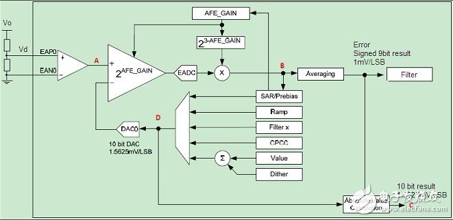
To enrich the flexibility of the application, the reference value (digital) set by the user is added to the output value (digital quantity) of the EADC to generate a digital signal called "absolute value", which can represent the actual acquired value. Voltage information (ie the value of Vd).
The digital comparator of UCD3138 uses digital error signal (point B value) or absolute value (point C value) as one input terminal, reference voltage value (user can set it by itself) as the other input terminal, which can be configured after triggering. It shuts down any DPWM.
There are 3 AFE modules in the UCD3138, and similarly there are 4 digital comparators.
1.2 Key Comparators involved in digital comparators
1.2.1 Output of EADC
The output of EADC is the amount of information after the digitization of the reference voltage and the input analog value, that is, the amount of digital error, the range of which is directly related to the gain of the AFE itself. For example, when the gain value is set to 1, its output range is +248~-256; when the gain is set to 8, the output range is +31~-32.
Bits 0~8 of the EADCRAWVALUE register (9 bits in total, named RAW_ERROR_VALUE) store the output of the EADC with a resolution of 1mV/bit.
1.2.2 DAC input
The output of the DAC is the reference voltage of the system. In the practical application of the UCD3138, the user can set the input value of the DAC as a digital semaphore. Bits 4~13 of the EADCDAC register (10 bits in total, named DAC_VALUE) hold the user's settings. The resolution is 1.5625mV/bit.
1.2.3 The 16th to 25th digits of the absolute value register EADCVALUE (10bit total, named ABS_VALUE) holds the absolute value and the resolution is 1.5625mV/bit.
As mentioned above, the absolute value is the sum of the output information of the EADC and the input information of the DAC, but it is not the direct addition of the two digital quantities because of their different resolutions. In fact, there is an equation relationship between the analog quantities represented by the above three digital quantities.
For example, under certain conditions, the output of EADC (ERROR_VALUE) is 192; the input of DAC is 747; the absolute value (ABS_VALUE) is 624, as shown in Figure 2 below. 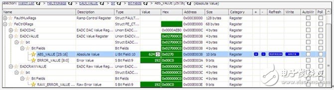
Figure 2. Register values ​​read in Memory Debugger
Obviously, 747-624=123≠192. However, the respective analog quantities satisfy the equation relationship as follows:
The analog output of EADC output 192 is 192 & TImes; 1mV / bit = 192mV;
The analog input of the 747 input 747 is 747 & TImes; 1.5625mV / bit = 1167.1875mV;
The absolute analog quantity 624 corresponds to the analog quantity is 624 & TImes; 1.5625mV / bit = 975mV;
◎ Finally, 1167.1875-975=192.1875≈ 192.
Alternatively, the three digital quantities may have the following equation relationship after increasing the attenuation coefficient: 
1.3 Digital Comparator Software Configuration <br> During the program initialization phase, the configuration of the digital comparator can be completed. Take the configuration of the digital comparator 0 as an example, the main code is as follows:
FaultMuxRegs.DCOMPCTRL0.bit.CNT_THRESH = 1;
The above code configuration only needs to trigger the digital comparator once to generate a fault.
FaultMuxRegs.DCOMPCTRL0.bit.FE_SEL = 0;
The above code configures the input of the digital comparator to be the absolute value of AFE0. It can also be configured as the output of the EADC. In addition, the absolute value of the remaining two AFEs and the output of the EADC can also be configured as inputs to digital comparator 0.
FaultMuxRegs.DCOMPCTRL0.bit.COMP_POL = 1;
The above code is configured to trigger when the input of the digital comparator is higher than the reference amount.
FaultMuxRegs.DCOMPCTRL0.bit.THRESH = 850;
The reference amount is set to 850. If the input is selected as an absolute value, the digital comparator is triggered when the Vd voltage is greater than 850 & TImes; 1.5625 mV/bit = 1.33 V.
FaultMuxRegs.DPWM0FLTABDET.bit.DCOMP0_EN=1;
The above code is configured to turn off DPWM0A and DPWM0B immediately after the digital comparator is triggered.
â– Good heat dissipation
--Blade design of copper alloy contacts,good conductivity
â– Super high impact resistance and thermal stability
--Cover pans are made of high quality polycarbonate
â– Chemical corrosion resistance
-- Fingerprint-resistant zinc plated mounting brackets
â– Grounding
--One-piece grounding design,No Load-Weather resistance
Digital Power Controller UCD3138 Digital Comparator and Analog to Digital Converter Application Note
Abstract <br> The digital power controller UCD3138 is internally integrated with 4 digital comparators for flexible configuration of its inputs and reference values. The absolute value of the analog front end (AFE) module and the output of the EADC can be used as inputs to the digital comparator, so the digital comparator can be used to provide fault response and protection to the system output voltage. The UCD3138 integrates 16 analog-to-digital converters (ADCs). The analog-to-digital converter named ADC15 is not open to the outside. It can be used to detect EAP or EAN pins of any of the three AFE modules to achieve system output voltage. The precise acquisition can ultimately achieve fault response and protection against the output voltage.
Figure 1. UCD3138 AFE Module Block Diagram