Abstract: According to the requirements of petrochemical company, a remote on-board monitoring system based on GPRS wireless network and embedded operating system μC/OS-II was designed to monitor the storage temperature and geographical location information of tank tank tank. The vehicle planting terminal adopts virtual IP wireless network technology and GPS satellite positioning technology. The data monitoring center designed the GPRS data receiving software based on UDP protocol and adopted the Access database link technology to successfully realize the on-site collection and remote reception of remote vehicle information. Finally, the running results of the system are given. This article refers to the address: http://
Coupletech Co., Ltd. supply diode-pumped Pulsed Solid-state laser and passive Q-Switched Pulse Laser models, in particular, athermal diode-pumped Pulsed solid-state Laser 1064nm without temperature control can work from -40℃ to +60℃ and diode-pumped Pulsed solid-state Laser with air-cooling can work from -40℃ to +60℃ for Laser Distance Measuring, and the power is >100mJ for the repetition of 1-100Hz. Passive Q-Switched pulse laser models consist of Mid-infrared laser MP-3200, Eye-safety Laser MP-1570, Infrared laser MP-1064, Green laser MP-532, UV laser MP-355, Deep UV laser MP-266, and these products cover a wide range of wavelengths: 3200nm, 1570nm, 1064nm, 532nm, 355nm and 266nm, with operating temperature of 10 ~ 35℃, the average power is 0 ~ 200 mW for the repetition of 20kHz.
Coupletech's Pulsed solid-state laser has advantage of compact athermal resonator design, no significant warm up time, no power consuming cooling system, no diode technology for increased efficiency and long life performance, no high energy with low beam divergence and Shock and viabration hardened.
Diode Pumped Pulsed,Laser Diode Module,High Power Laser Diode,Diode Pumped Laser,Eye-safety Laser Coupletech Co., Ltd. , https://www.coupletech.com
Keywords: GPRS network; GPS; database; vehicle monitoring system
0 Introduction With the advent of the post-PC era, the application of embedded systems has become more and more common, and remote monitoring systems based on GPRS wireless networks are also widely used in many industrial engineering fields. This paper will describe the embedded remote on-board monitoring system based on GPRS wireless network, which is used for remote monitoring of tank storage tank temperature and geographical location information. The purpose is to enable the petrochemical company to keep abreast of the temperature of the tank during transportation. The change status of the site plays an early warning role in preventing the storage tank from causing danger due to temperature overrun, ensuring the safety of the railway transportation of the storage tank. This paper focuses on the implementation of its system and vehicle GPS satellite positioning technology and wireless data transmission of remote data.
1 System implementation and structure The entire vehicle system can be divided into two parts: the vehicle terminal and the monitoring data center, as shown in Figure 1. At the heart of the vehicle terminal is the 16/32-bit RISC microprocessor S3C24 40A from Samsung. It has three serial ports, in which serial port 1 is connected to GPRS wireless transmitting module, serial port 2 is connected to GPS satellite positioning module, and its own A/D conversion interface is used to complete the conversion of analog signal to digital signal. The collected positioning data and temperature data are sent to the remote data monitoring center via the GPRS wireless network, and the monitoring center stores the received data in a local database for query and reference. 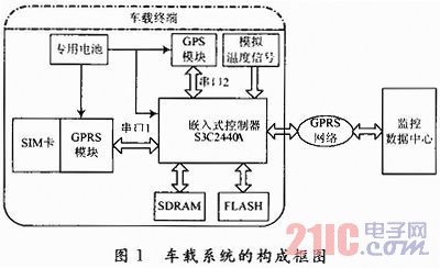
2 Design of vehicle terminal data acquisition module and GPRS wireless transmission module
2.1 Design of Vehicle Terminal Data Acquisition Module The vehicle terminal data acquisition module includes the collection of tank storage temperature and GPS satellite positioning data. Its circuit schematic is shown in Figure 2. The left end of the figure is the temperature acquisition schematic. The temperature transmitter can be used to convert the tank storage temperature into a standard current output of 0-40 mA. After passing through the varistor, the current can be converted into an ARM microprocessor. Analog voltage, voltage range should be controlled from 0 to 3.3 V. The right end of Figure 2 is the GPS data acquisition schematic. The GPS receiver adopts the latest GPS navigation module REB-1315 from Taiwan Dingtian International. 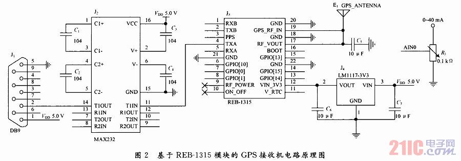
The module's supply voltage is 3.3 V DC, which is obtained by converting 5 V DC through the LM1117 chip. The 19-pin GPS_RF_IN is the GPS signal input terminal, which is connected to the GPS receiving antenna, and is supplied with a bias voltage by the module's own 17-pin RF_VOUT signal to ensure the normal operation of the antenna. The 4-pin TXA sends a signal to the serial port of the module. It is the main data transmission channel of the module and is used to output positioning data. This design uses it to obtain positioning information. Since the output of the REB-1315 module is TTL level, the MAX232 is used to convert the signal level to the RS 232 level. For convenience, the DB9 pin 1 is used to provide a 5 V DC input voltage to the module. When the module GPS antenna is connected and powered up, the GPS positioning data will be continuously output from the 4th pin. The right side of Figure 2 is the A/D acquisition interface. The standard output of the temperature transmitter is 0~40 mA. It is converted into the analog voltage of 0~3.3 V through the varistor and sent to the analog channel AIN0 of S3C2440A for A/D. Conversion.
2.2 Design of GPRS wireless transmitting module The GPRS module of the vehicle terminal adopts Huawei EM310 module, and the circuit schematic diagram of GPRS wireless transmitting module based on EM310 module is shown in Fig. 3. The module's power supply voltage is 3.8 V. The 1 to 6 pins are the SIM card control interface, the 13 pins are the network connection status indication interface, and the serial port 0 is used to communicate with the MCU. 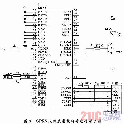
3 Software design of the vehicle terminal The software writing language of this system is C language, and it is compiled and debugged by ARM Developer Suite v1.2 integrated development environment. This is a multi-tasking system. The terminal needs to complete temperature acquisition, GPS satellite positioning data acquisition and wireless transmission of GPRS data at the same time. In order to meet the system needs, the embedded operating system μC/OS-II is used to realize multi-task scheduling. The design process of the operating system is shown in Figure 4. 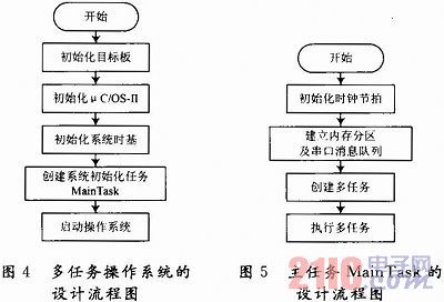
The operating system initially completes the initialization of the vehicle terminal hardware board, and then initializes μC/OS-II. μC/OS-II is a real-time operating system, which has very strict requirements on the system clock, so it is necessary to initialize the time base of the system. In order to ensure the portability and integrity of the operating system, initialization tasks such as serial port initialization and interrupt are performed in the initialization task MainTask. Finally start the operating system. Temperature acquisition of the vehicle terminal, GPS satellite positioning data acquisition and wireless transmission of GPRS data are established in the MainTask as three independent and closely connected tasks, and the priorities of the three tasks are sequentially reduced. The design flow chart of the main task Main Task is shown in Figure 5. The clock tempo is initialized first, because all tasks in the operating system are executed accurately under the action of the clock tempo. Then create a memory partition and serial message queue, and finally establish and execute multitasking. Here, the message mailbox mechanism of the μC/OS-II operating system is utilized, and the A/D acquisition result and the GPS satellite positioning data are sequentially delivered to the message queue, and when the GPRS task is executed, they are respectively taken out from the message pair column to be sent. .
Since A/D acquisition is relatively easy, the following only introduces the acquisition of GPS satellite positioning data and the wireless transmission process of GPRS data.
3.1 GPS satellite positioning data acquisition process GPS satellite positioning data acquisition includes GPS positioning information extraction, analysis and message delivery, including all the steps and methods of GPS data processing. The program flow chart is shown in Figure 6. 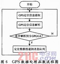
The extraction, parsing and message delivery of GPS location information are performed in the while(1) loop. Before posting the location information, it is necessary to determine whether to parse the $GPGGA data frame. The GPS data processing function GPSproc() code is as follows: 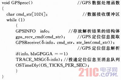
The program first extracts the positioning information into the data buffer, and then parses the data into the defined structure. The data members of the structure include time, longitude and latitude and the $GPGGA data frame flag. When the $GPGGA data frame is reached, the message delivery work is performed. For GPS positioning information analysis function void GPSReceire (GPSINFO* info, UInt8*pStrearn, UInt8len), it is the most critical step to obtain positioning data. It needs special explanation here, and its working flow chart is shown in Figure 7. In order to ensure the reliability and accuracy of the data, it is necessary to perform an exclusive OR check on each frame of data. If the XOR check is correct, the effective fields in the data frame are extracted and processed. 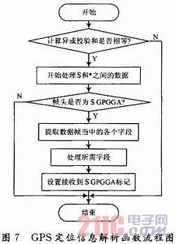
3.2 GPRS data network purchase solution The key to remote data transmission of vehicle data remotely is the establishment of GPRS wireless network channel. In practical applications, the public network static IP, dynamic domain name resolution, short message communication, APN private line access and other networking solutions can be utilized. However, the static IP of the public network requires a considerable part of the usage fee, which is not conducive to the reduction of system development costs. The stability of the dynamic domain name resolution scheme is subject to the DNS server and requires a certain development cost. Short message communication is easy to receive interference and is not real-time. The APN private line access solution is usually suitable for occasions with high security requirements, high monitoring points, and high real-time requirements, but this technology is more complicated to use.
In view of this, the system adopts virtual IP technology, which is an e-mail-like technology, which is suitable for occasions requiring static IP of the public network. The networking is convenient, and the data can be arbitrarily transferred in different network segments through a remote server. The network structure is shown in Figure 8. 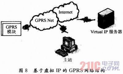
The GPRS module uses a SIM card to log in to the mobile Internet, and the computer at the primary station also accesses the Internet. Assign the GPRS module and the primary station computer a virtual IP address of equivalent status (here 10.1.90.0 and 10.1.90.1 respectively). For a remote virtual IP server, it can be built by itself or by a commercial company. Since it can receive data and provide download services arbitrarily in different network segments, it has a public network static IP. In order to unify it, it is also I assigned my own virtual IP address and it is also set to the corresponding port number (here 7002). In the application, the vehicle GPRS module sends the first collected data to the server according to the UDP datagram, and then the server will parse the datagram and forward it to the target IP address, and the primary station is also running on the monitoring center computer. The data receiving software of the UDP protocol, thus realizing the transmission of the vehicle data to the remote monitoring center. The structure of the UDP datagram is shown in Table 1. If the terminal numbered 10.1.90.1 sends the string ABCD and the service password is 123456, the datagram is: 0A015A000A015A01313233343536000441424344. If the content of the transmission contains Chinese characters, it is GB2312 Chinese character code. 
3.3 GPRS module to send data operations To enable the GPRS module to establish a network connection and achieve remote data transmission is achieved by sending a series of AT commands to the control serial port. For the EM310 module, the main AT commands used are as follows: 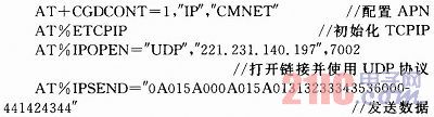
In the GPRS task of μC/OS-II, the above AT command is written into the C language code, that is, written into the serial port printing operation statement, in order to make the GPRS module hardware better respond to the command, it is required in each instruction. After a delay of a few seconds. The data sent is taken from the message queue.
4 System operation results The vehicle terminal uses the embedded integrated development software ADS 1.2 and is written in C language. The data receiving software of the data monitoring center uses MFC design, and also uses ADO technology, which can store the received data in time to the local Access database through processing, and can also provide the staff to query the database information at any time. 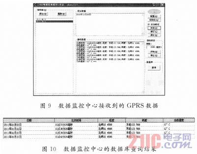
FIG. 9 is a case where the data center receiving software receives the remote GPRS data, and FIG. 10 is a query result of the database. It can be seen that the system has achieved good results during the test run.
5 Conclusion Although the system conducts research on the monitoring of tank trucks in petrochemical enterprises, its technical solutions and technical achievements will be extended to product transportation in other industries, remote monitoring and control of industrial and industrial equipment operation status, and telemedicine. And many other fields have broad application prospects.

