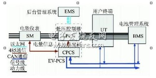
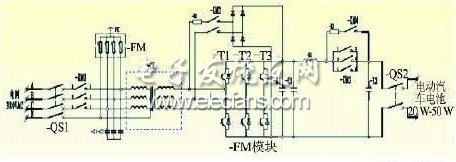
The core value of the smart grid is to improve energy efficiency, use various high-tech means to improve the operation and management level of all links of transmission, transmission, distribution and power consumption, save resources and protect the environment; smart grid is more suitable for power generation and distribution of multiple energy units. The need of electricity consumption is more suitable for the needs of market-oriented power trading, and is more suitable for customers' self-selection needs. Vehicle to Grid ( V2G ) technology is the two-way interaction and exchange between the energy of electric vehicles and the grid under controlled conditions. It is an important part of “smart grid technologyâ€, applying V2G and smart grid technology. The charging and discharging of the electric vehicle battery is uniformly deployed. According to the established charging and discharging strategy, the remaining electric energy can be controlled and fed back to the power grid in two directions under the premise of satisfying the driving demand of the electric vehicle user. 1 V2G system information flow V2G embodies energy bidirectional, real-time, controllable, flowing between the vehicle and the grid. The charge and discharge control device has interaction with the grid and interaction with the vehicle. The interactive content includes energy conversion information, customer demand information, Grid status, vehicle information, metering and billing information, etc. Therefore, V2G is a high-end integrated application of many technologies such as power electronics, communication, scheduling and metering, and demand side management. Figure 1 shows the V2G system information map. SM: smart meter, two-way metering, local information storage, communicate with EV2PCS via RS485, and transmit power information to the UT through EV2PCS; EV2PCS: Two-way intelligent charging and discharging device, which consists of a low-voltage controller and a local management machine, is used to realize two-way energy interaction between the vehicle and the power grid, and is a key device of the V2G system; UT: Human-computer interaction terminal is an interface between the electric vehicle user and the power grid, and the user obtains the power consumption and electricity fee information from the user; BMS: Battery management system, used for collecting and transmitting vehicle battery data, monitoring battery operating status, communicating with EV2PCS via CAN bus, transmitting vehicle information to the background through EV2PCS; EMS: The background management system communicates with the power grid dispatching system, obtains the grid load information and executes the grid dispatching command, communicates with the EV2PCS, acquires the vehicle state information, and assigns and dispatches the power grid dispatching command. 2 V2G system components 2. 1 bidirectional intelligent charging and discharging device As a key power component in V2G technology, the two-way intelligent control device is used to realize the bidirectional flow of energy between the power grid and the electric vehicle. It can work in the charging mode and the V2G mode: if the charging working mode is selected, only the charging operation of the vehicle is performed, The vehicle battery energy is fed back to the power grid; if the V2G working mode is selected, the device can charge and discharge the connected vehicle according to the upper and lower thresholds of the vehicle SOC selected by the user on the human-machine interaction terminal, or the default upper and lower thresholds of the SOC of the device. The real-time capacity, controlled time and other information are provided to the background management system, and the background management system issues a charge and discharge control command, and the device performs charging and discharging operations according to the current SOC of the vehicle battery to realize two-way flow of energy. Figure 2 shows the main loop topology of the two-way intelligent control device. Its topology features are as follows: (1) Three-phase full-bridge bidirectional PWM conversion can be used to charge and discharge the battery; (2) Grid communication and electric vehicle battery side are electrically isolated by isolation transformer (3) At the same time, the isolation transformer can perform voltage matching between AC and DC; (4) An overload overcurrent circuit breaker is configured on the AC side and the DC side; (5) The AC DC side is equipped with a pre-charging circuit, and the starting mode is flexible; (6) Adopting a first-stage converter, the topology is simple and the reliability is high. 2. 2 human-computer interaction terminal The structure of the human-computer interaction terminal system is shown in Figure 3. It is mainly composed of an embedded controller, a touch display screen, a radio frequency card reader, a CAN communication card, a remote monitoring communication expansion card, and a micro printer. The main functions are: interface display, identification, EV2PCS control mode, ticket printing, data management and query, personalized parameter setting, language switching, user operation help and abnormal information prompts. Figure 3 shows the structure of the human-computer interaction terminal system. Figure 8 Self-Supporting Optical Fiber Cable Figure 8 Cable,Figure 8 Self-Supporting Optical Fiber Cable,All Dielectric Self-Support Cable,Self Surpporting Aerial Shandong Qingguo Optical Fiber Co., Ltd. , https://www.qgfiber.com