When the frequency conversion-power frequency is switched, the frequency conversion bomber appears, and there is an open trip. Therefore, various explanations have appeared, which makes the frequency conversion-power frequency switching become an insurmountable threshold. Operational notes: 1, to switch the power frequency of the motor, the parking mode is set to free parking, should not be soft parking; plc data network 4. The other is that the motor has not completely left the inverter (for example, the arc has not been extinguished), and the power frequency is switched out too early to form a power frequency short circuit;
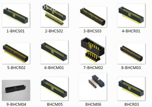
Antenk box header connector,Those products are used in more or less every known application within computer-, industrial-, telecommunication and specific automotive markets. This product technology allows cost effective connections between printed circuit boards based on removable or permanent connections based on a longterm proofed way of assembly. box header connectors are available with the traditionally used pitch of 2.54mm and the pitch of 2.00mm,1.27mm.
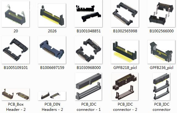
Antenk Box header/Ejector header Description and Application:
Box header
Ejector header
Box Header,Box Header Connector,Ecu Box Header Connector,Latch Box Header Connector,1.27mm Box Header Connector,2.00mm Box Header Connector,2.54mm Box Header Connector ShenZhen Antenk Electronics Co,Ltd , http://www.coincellholder.com
For example, some people say "must ensure that the phase sequence of the inverter output and the power frequency phase sequence are the same, so that it is possible to cut in" and so on. If the phase sequence of the inverter output and the power frequency are in the same phase sequence, the frequency conversion-power frequency switching will change the frequency converter and the air-opening will trip. Obviously the reason is not because of the phase sequence, phase, etc.
I will tell you a simple method. You use a voltmeter to measure the voltage between the inverter output and the power frequency phase line. No matter how you adjust the phase sequence, phase or other of the inverter output, the measurement result is the power frequency 380V line voltage. .
The voltage between the inverter output and the power frequency phase line is the power frequency 380V line voltage. Can you directly perform the frequency conversion-power frequency switching? Can you switch directly without a bomber or trip?
Therefore, the technical secret of frequency conversion-power frequency switching is that the output end of the frequency converter cannot be short-circuited with the power frequency. As long as the output end of the frequency converter and the power frequency are not short-circuited, your method will ensure the successful switching.
How to ensure that the output of the inverter is not short-circuited with the power frequency? The method is very simple. You use a contactor 1 to disconnect the inverter output from the motor, then use a contactor 2 to connect the power frequency to the motor, and use the normally closed contact of the contactor 1 to turn on the electromagnetic of the contactor 2. The coils, ie the contactor 1 and the contactor 2, must be interlocked. This ensures that the output of the inverter and the power frequency cannot be shorted, and your switch will no longer explode or trip.
2. Cut off the contactor of the motor from the output end of the inverter. The control stop button and the stop button of the inverter are the same composite button. When the parking is stopped, the inverter stops and the contactor coil is cut off to cut off the connection between the motor and the inverter.
3. Cut off the contactor of the motor from the output end of the inverter, and the control start button and the start button of the inverter are interlocked, that is, after the contactor is turned on, the inverter can be started;
4. The motor is connected to the power frequency contactor, and the coil control loop is controlled by the inverter output terminal to cut off the normally closed contact of the contactor of the motor to ensure that the inverter output terminal cuts off the motor and then accesses the power frequency;
5. If the switching process is fast and accurate, that is, the shorter the time that the motor is out of the power supply inertia operation, the less the speed drop, the less the “shockâ€, the motor is switched at the rated current;
6, here should pay attention to the phase sequence of the motor connected to the power frequency to ensure that the motor is switched after switching!
7, the power frequency to the motor should be provided with an isolation circuit breaker;
"Switching 400KW motor, the high voltage side is tripping"
1. It seems that everyone has doubts about switching power frequency of high-power motors;
2. I am worried about generating electricity during the inertia of the motor. It is not necessary, but what causes the trip?
3. There are two problems worth considering. One is that after the large motor is disconnected from the power supply, the winding has an electrostatic voltage due to the distributed capacitance, and an operating overvoltage occurs during switching;
5, the solution is to first let the frequency converter free stop, the motor then leaves the inverter, and then switch to the power frequency, you can discharge the switch trip caused by the above reasons;
6, must control the time difference! ! !
Switching between frequency conversion and power frequency, when using PLC to control the switching process, the secret of switching is that the frequency conversion free stop to the cutting motor should have a delay of 0.1 seconds. The motor should be cut from the frequency conversion to the power frequency to have 0.2--0.4 seconds. Delay, the entire process is completed in 0.5 seconds;
Box header/ ejector header connector, With DIP straight/vertical, SMT,Right angle, 2.54pitch, 2.0pitch, 1.27pitch,
The commonly used Pin ways have 6P,8P,10P,14P,16P,20P, 24P,26P,30P,34P, 40P,50P,64P.
Box header/ ejector header and IDC Flat Cable connectors are two of the most commonly used connectors. Box headers can be found in nearly all electronic equipments.
This is a IDC product which allows cost effective connections between circuit boards based on permanent connection (using transition connector) or removable connection
(Using for IDC flat cable connectors).

