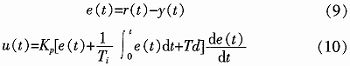
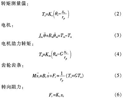
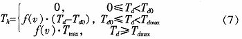
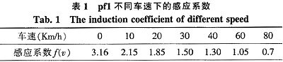
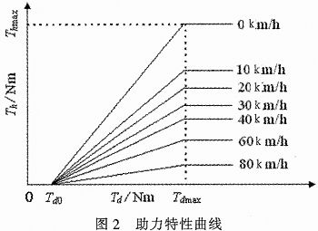
Abstract: The working principle and mathematical model of electric power steering system (EPS) are analyzed. The linear EPS assist characteristic curve and the incremental closed-loop PID control strategy are established. With MC9S12DP256 MCU as the core, the controller power supply circuit, signal processing circuit, CAN communication circuit and clock circuit are designed, and the software design flow is given. This design utilizes the rich internal resources of MC9S12DP256, introduces CAN technology, simplifies the hardware circuit, reduces the interference between circuits, and improves the reliability of the control system. This article refers to the address: http:// Key words: electric power steering; PID control; CAN; MC9S12DP256 The steering system is an important part of the car, and its performance directly affects the stability and safety of the car. The early car steering system was a purely mechanical steering system with no power. The steering power was completely provided by the driver and the driving experience was poor. Since the 1930s, power steering systems have emerged. At present, there are three main forms of automotive power steering: Hydraulic Power Steering (HPS), Electric Hydraulic Power Steering (EHPS), and Electric Power Steering System (EPS). ). Compared with the first two, EPS provides auxiliary torque from the motor, without oil system, which greatly reduces the complexity of the steering system of the car, and has obvious advantages in fuel efficiency, modularity, power-assisting effect and environmental friendliness. . According to the position of the EPS assist motor on the gear and the steering column assembly, the EPS system is divided into four types: steering column assist type, rack assist type, pinion assist type and double pinion assist type. Pinion and steering column assist are used in light vehicles, and double pinion assist is used in heavy vehicles. They are composed of three basic components: an electric control unit (ECU), a booster motor and a torque sensor mounted on the steering column. For the small car, the EPS controller is designed with the 16-bit single chip MC9S12DP256 of Freescale Company as the core. 1 Electric power steering system structure and working principle The structure of the electric power steering system is shown in Figure 1. It is mainly composed of a steering wheel, a torque sensor, an electronic control unit (ECU), a motor, an electromagnetic clutch, a speed reduction mechanism, and a rack and pinion steering gear. After the engine is ignited, the steering torque is measured by a torque sensor mounted on the steering shaft and sent to the ECU. The ECU calculates a boost characteristic curve and a control strategy based on the torque and the vehicle speed. The optimum current required by the motor, thus controlling the output torque and direction of rotation of the motor, and then applying it to the steering mechanism via the reduction mechanism, ultimately resulting in a steering force that is compatible with the driving conditions to assist the driver in steering. 2 control strategy 2.1 Establishment of EPS model According to Newton's law, a mathematical model of the steering system can be established. Where: Th is the steering wheel input torque, Js is the steering column, the disk assembly moment of inertia, Bs is the input shaft damping coefficient, Ks is the torque sensor stiffness coefficient, Tm motor output torque, Km is the stiffness coefficient of the assist motor and the speed reduction mechanism, Jm is the driving motor moment of inertia, Bm is the assist motor damping coefficient, M is the rack quality, Br is the rack and steering wheel viscous damping coefficient, Kr is the rack equivalent stiffness, G is the assist mechanism transmission ratio, and rp is the pinion radius , θs is the steering wheel angle, θm is the motor rotation angle, xr is the rack displacement, and Fr is the steering resistance. 2.2 Assist characteristic curve design The EPS assist characteristic is the relationship between the driver input torque and the motor assist torque (assisted current). During the driving process, the steering resistance decreases as the vehicle speed increases. In order to obtain the portability of the steering at low speed and the stability during high-speed driving, the motor assist torque decreases with the increase of the vehicle speed under the same driving conditions, and the motor does not assist when the vehicle speed exceeds a certain range. . There are three common power assist curves: linear, polygonal, and curved. The linear assist characteristic curve is simple in form and easy to adjust and implement in practice. Therefore, the linear boosting characteristics are used in the design of the controller. The linear assist characteristic can be expressed as the following functional relationship: Among them: Th is the motor target torque, f(v) is the vehicle speed induction coefficient, Tmax is the motor maximum assist torque, Td0 is the driver input minimum torque when starting power, and Tdmax is the driver input torque when the motor provides maximum power. The assist characteristic parameters are determined: Td0 = 1 Nm, Tdmax = 7.6 Nm, Thmax = 21 Nm. The vehicle speed induction coefficient is determined according to the rules shown in Table 1 (final correction is required after the actual vehicle test). When the vehicle speed exceeds 80 km/h, the motor does not assist. According to the above parameters, the power assist characteristic curve design is shown in Figure 2. The motor target current can be obtained from equation (8): Where ki is the motor torque factor and G is the motor reduction mechanism transmission ratio. 2.3 Control algorithm The EPS system control is the control of the magnitude and direction of the motor current. The quality of its control algorithm directly affects the performance of the steering system. This paper adopts the PID control algorithm widely used in the field of industrial control. The PID control has high stability and reliability, strong real-time performance, simple control and debugging method, and is easy to implement. It is suitable for the control of automotive electric power steering system. Therefore, PID control is the main control strategy of the current EPS control system. The expression of the PID control can be expressed as: Where: r(t) is the target value of the assist motor current, y(t) is the actual output value of the control system, u(t) is the output signal of the PID controller, Ti is the integral time constant, and Td is the differential time constant. The core of the EPS control system is a microcontroller that uses digital signals. Therefore, the following formula (10) needs to be processed: YZF series shaded pole motors are with single phase,4 poles and running at voltage of 220-240V,50/60HZ or 110-120V,60HZ.Widely used in the radiator,evaporator,refrigerator,fridge and othe refrigeration equipment.All material conform to ROHS.The output power is from 2W to 34W,which is relative to the stack length and coil parameters.The insulation class of motors is B,and the protection class of that is IP42.The applicable ambient temperature is from -30C~50C.The average service life of motors is over 20000hours. There are screw holes on the end cover; bracket installation; grid installaton; flange installation; also we can customize according to your request.We can custom-made motor with different voltage, frequency, wire length, bearing, special use of the environmet etc. Evaporator Fan Motor,Fan Motor,Metal Ec Motor,Electric Ec Motor ZHEJIANG ICE LOONG ENVIRONMENTAL SCI-TECH CO.,LTD. , https://www.china-refrigerantgas.com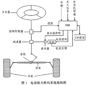
![]()
![]()