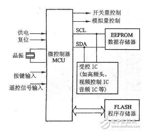
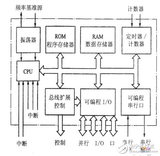
The basic block diagram of the PDP color TV microcontroller circuit is shown in the figure below. As can be seen from the figure, the microcontroller circuit is mainly composed of MCU and working condition circuit (power supply, reset, oscillation circuit), remote control receiving circuit, key input circuit, EEPROM data memory, Flash program memory, and switching control circuit (output level). Level), analog control circuit (output PWM pulse signal), I2C bus (parallel bus, serial bus, SPI bus) control circuit. The following is a brief introduction. 1. MCU and memory Most of the PDP color TVs use a microcontroller with 51 MCU as the core. It provides all the resources (ROM, I/O interface, etc.) that can be developed to the color TV manufacturer. The manufacturer can design the interface and program according to the needs of the application. Therefore, it has strong adaptability and is widely used. The figure below shows the block diagram of the MCU hardware. As can be seen from the figure, a basic MCU is mainly composed of the following parts: (1) CPU: The CPU plays a central role in the microcontroller. The receiving and executing instructions, various control functions, and auxiliary functions of all the operating action commands of the microcontroller are performed under the management of the CPU. At the same time, the CPU has to perform various computing tasks. (2) Memory: The internal memory of the MCU consists of two parts: 1 Random access memory RAM: used to store the intermediate data of the program running. During the working process of the microcontroller, the data may be rewritten, so the contents stored in the RAM can be changed at any time. It should be noted that after the color TV is powered off and the power is turned off, the data stored in the RAM will disappear. 2 read-only memory ROM: used to store programs and fixed data. The so-called program is a set of ordered instructions compiled according to the requirements of the problem to be solved and the instructions contained in the instruction system. The so-called data is the information, variables, parameters, tables, etc. in the MCU work process. When the color TV is turned off and the power is turned off, the programs and data stored in the ROM will not disappear. (3) Input/output (1/O) interface: The input/output interface circuit refers to the connection channel between the CPU and external circuits and devices and related control circuits. Due to the level of the external circuit and equipment, data format, operating speed, working mode, etc. are not uniform, in general, it is not compatible with the CPU (that is, it cannot be directly connected to the CPU). These external circuits and devices can only transmit and exchange information with each other through the input/output interface, so that the CPU can work in coordination with external circuits and devices. There are many types of input/output interfaces. Different external circuits and devices require corresponding input/output interface circuits. The method of programming can be used to determine the working mode, function and working state of the interface. Input/output interfaces can be divided into the following three categories: 1 Parallel input/output interface: Each lead can be flexibly selected as an input lead or an output lead. Some input/output leads are suitable for direct connection to other circuits, and some interfaces provide a large enough drive current. In the PDP color TV, the digital control pin and the analog control pin are parallel input/output ports. In addition, some MCUs allow the input/output interface to be used as a system parallel bus to extend the parallel bus memory and interface chip. 2 Serial Input/Output Interface: It is the simplest electrical interface. When serial communication with external circuits and devices, only a few signal lines are used. In PDP color TV, the serial input/output interface mainly has IIC serial bus interface (mounting EEPROM data memory and other IC with IIC bus interface) and SPI bus serial bus interface (mounting Flash program memory with SPI interface) ) two types. (4) Timer/Counter: In many applications of the MCU, it is often necessary to perform precise timing and generate a square wave signal, which is done by a timer/counter. Some timers also have an automatic reload function, which is more flexible and convenient to use, and it is easy to generate a programmable clock. When working in counter mode, pulses can be input from the specified input and counted. (5) System bus: Each basic circuit of the MCU is connected through an address bus (AB), a data bus (DB) and a control bus (CB), and then communicates with a circuit external to the MCU through a parallel input/output interface.
Plastic Jar Food Processors have light weight and easy to carry. And their price is cheaper than Glass Jar Food Processors, cost-effective.
Description for Plastic Jar Food Processors
350W/450W/600W
Including juicer, 1.25L plastic jar blender, chopper and grinder
2 speeds wth pulse
Carton box: 49.5*44.5*61cm 4pcs/ctn
20'GP: 912pcs 40'HQ: 2104pcs
Plastic Jar Food Processors Plastic Jar Food Processors,Baby Food Processor,Plastic Jar Processors,Plastic Food Processors Flying Electronic Co., Ltd , https://www.flyingelectronic.com