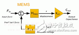
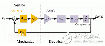
The high dependence of sensor performance on MEMS and ASIC parameters suggests that the system-level design of closed-loop sensors requires a number of trade-offs, with ASIC noise budgets, excitation voltages, power dissipation, and techniques all highly dependent on MEMS parameters. Therefore, in order to achieve an optimal sensor, an ASIC and MEMS collaborative design method based on the overall target specification of the sensor is strongly recommended, rather than an ASIC design for the already designed MEM. Micromechanical inertial sensors have become an integral part of many consumer products, such as handheld mobile terminals, cameras and game controllers. In addition, micromechanical inertial sensors are widely used for vibration monitoring in industrial, automotive safety and stability control, and navigation. In general, miniature sensors can be piezoelectric, piezoresistive or capacitive sensors. However, the high thermal stability and high sensitivity of capacitive sensing make it more attractive for a wide range of applications. The basic capacitive sensor interface circuit with digital readout consists of a capacitor-to-voltage converter (C/V) followed by an analog-to-digital converter (A/D) and signal conditioning circuitry. Operating this sensor in an open loop configuration (without feedback signals) can result in a relatively simple system that is inherently stable. However, systems that operate in open loop are very sensitive to MEMS parameters. In addition, the linearity of the entire system is affected by the linearity of each module in the sensor system chain, and the dynamic range requirements of C/V and A/D may be more stringent. Conversely, the use of MEMS sensors in a negative feedback loop has many benefits, such as improved bandwidth, lower sensitivity to process and temperature variations of MEMS devices. In addition, since C/V only needs to process the error signal, the C/V dynamic range and linearity index can be relaxed compared to the open-loop mode of operation. Therefore, to ensure the stability of the system, it is very important to design the feedback loop correctly. In a capacitive sensor, the feedback signal is applied to the MEMS as a voltage signal on the capacitive excitation electrode. This applied voltage will generate an electrostatic force and act on the MEMS mass. The resulting system is therefore called the force feedback system. However, the capacitor has a secondary voltage-to-force relationship that limits the linearity of the system. One way to overcome the burden of the secondary force of the voltage specific force (V/F) is to apply the excitation signal in a differential manner to cancel the quadratic term. However, this technique requires positive and negative voltage values, which will increase the complexity of the sensor interface ASIC. More importantly, if the two excitation capacitors required for differential operation do not match, the excitation quadratic term cannot be completely cancelled, so the capacitor mismatch will limit the performance that the system can achieve. Another way to achieve closed loop operation is to use a two-stage bang-bang feedback signal. Since only the secondary V/F relationship of two points is used, this method is inherently linear and does not rely on the matching of MEMS capacitors or the use of a negative voltage to cancel the nonlinearity. Using two levels of excitation means converting information in the amplitude of the feedback signal into time information. Therefore, sigma-delta modulation can be an effective technique for implementing a closed-loop digital read sensor. In addition, the Σ-Δ based loop provides analog-to-digital conversion by default, so there is no need to use a separate A/D. Σ-Δ closed-loop architecture to represent the optimal architecture for high-performance digital read sensors. It is worth noting that the oversampling characteristics of the sigma-delta system cause the operating system to operate at relatively high frequencies, so the system becomes more susceptible to MEMS parasitic capacitance coupling. Nevertheless, the circuit technology that counteracts this coupling is very mature and can be implemented in the interface ASIC of the sensor. The architectural choice of Σ-Δ closed-loop sensors needs to be based on deeper techniques developed for electronic sigma-delta systems. However, Σ-Δ closed-loop sensors with natural electro-mechanical properties need to correctly understand the working principle and modeling mechanism of MEMS in system-level design and optimization. The detection part of a typical MEMS sensor behaves like a second-order lumped mass (damper) spring mechanical system with a single resonant frequency whose transfer function is as follows: Where Fin(s) is the input force (the Coriolis force when using the gyroscope and the acceleration generated by the input acceleration when using the accelerometer). x(s) is the displacement of the sensor mass corresponding to the input force. m is the mass of the mass, D is the damping coefficient, and k is the spring constant (stiffness). The working principle of MEMS sensors is based on the fact that applying an input force (Fin) to a MEMS will produce a certain displacement, which in turn changes the MEMS capacitance (Cout). This Cout can be measured with circuitry connected to the MEMS unit. The MEMS sensor with excitation electrodes is modeled as shown in Figure 1. The gain of this model is Kx/c, which represents the change in output capacitance due to MEMS mass displacement. Kx/c is equal to: Where Cd is the detection capacitance of the MEMS and X0 is the capacitance gap distance. A factor of 2 represents differential operation. This model also contains a KV/F factor, which is the force due to the feedback voltage VACT: Where VACT is the excitation voltage and Ca is the excitation capacitance of the MEMS. Pull-in (pull-in) is an important phenomenon of capacitive MEMS sensors. At this time, the capacitor plates are attracted together due to the applied large voltage, resulting in malfunction. The maximum quiescent voltage against pull-in is equal to: Where C0 is the remaining capacity of the capacitor. The above Vp expression is only used to demonstrate the relevance of Vp. Figure 1: MEMS Inertial Sensor Sensing Part Model But in the case of dynamic voltage excitation as in a Σ-Δ loop, the above expression does not accurately represent the actual value of Vp. In Σ-Δ based sensors, MEMS is used as a loop filter to form a second-order electro-mechanical Σ-Δ system. Introducing MEMS into the sigma-delta loop can increase the order and further suppress quantization noise. Figure 2 shows a block diagram of a sigma-delta based sensor in which the MEMS are connected to an application specific integrated circuit (ASIC) to form a complete sensor. The system also integrates an additional Hcomp block to compensate for the loop and maintain its stability. Figure 2: Block diagram of a closed-loop sensor based on Σ-Δ The system-level design of this closed-loop sensor will determine the optimum values ​​for various MEMS and ASIC parameters, such as stiffness (k), gap distance (X0), damping factor (D), excitation voltage (VACT), and ASIC noise. In order to ensure stable operation of the sigma-delta loop, the input signal of the sensor cannot exceed the feedback signal. Thus the excitation voltage value VACT defines the maximum input signal allowed for a given MEMS parameter set condition. However, generating a large VACT in order to allow a large input signal range results in increased power consumption and sometimes requires special ASIC technology to allow high voltage operation. The choice of ASIC technology will affect the overall cost of the sensor. More importantly, the maximum allowed by VACT is limited by the MEMS pull-in voltage Vp. The MEMS gap distance (X0) is a key parameter for the system to achieve low noise operation. Decreasing X0 produces higher Cd and Kx/c and thus increases the MEMS forward gain (sensitivity). High sensitivity reduces the effects of ASIC noise on noise referenced to the sensor input. On the other hand, the Brownian noise power of MEMS is directly proportional to the damping coefficient (D). The total sensor noise consists of MEMS noise and ASIC noise. The maximum tolerable ASIC noise value can be estimated based on the sensor's overall target performance, MEMS sensitivity, and damping coefficient. It should be noted that the minimum X0 that can be achieved is limited by MEMS technology. The effect of the X0 value on the maximum input range depends on whether the excitation voltage (VACT) is limited by the MEMS pull-in voltage. If VACT is limited by the pull-in voltage, then decreasing X0 will result in a reduction in the maximum allowable input signal range. If VACT is not limited by the pull-in voltage, then the reduction in X0 and the improvement in excitation capacitance (Ca) and KV/F can result in higher feedback forces, ultimately resulting in a larger input range. The stiffness (k) of a MEMS cell is an important system design parameter because it can be well controlled in MEMS cells, unlike X0, whose minimum is limited by MEMS technology. Assuming ASIC noise dominates sensor noise, the maximum achievable dynamic range (VACT is set to the maximum allowable value before snapping) will be independent of the first-order k value. This is because increasing k not only reduces MEMS sensitivity, increases ASIC noise referenced to the sensor input, but also increases the feedback force by the same amount because it allows operation at higher VACT. In the case of MEMS noise dominated sensor performance, the value of k should be increased to support a larger dynamic range. In the case where the work is not restricted by the pull-in, it is preferable to reduce the k value, thereby improving the sensitivity of the MEMS and reducing the influence of the ASIC noise on the sensor noise. It should be noted that the value of k changes the resonant frequency of the MEMS unit. In open-loop sensors, the resonant frequency sets the upper limit of the sensor bandwidth, which is not the case for closed-loop systems. Therefore the k value can be set according to the dynamic range and noise requirements. The high dependence of sensor performance on MEMS and ASIC parameters suggests that the system-level design of closed-loop sensors requires a number of trade-offs, with ASIC noise budgets, excitation voltages, power dissipation, and techniques all highly dependent on MEMS parameters. Therefore, in order to achieve an optimal sensor, an ASIC and MEMS collaborative design method based on the overall target specification of the sensor is strongly recommended, rather than an ASIC design for the already designed MEM.
Bluetooth Earbuds /Tws Earbuds /Sport Bluetooth Earbuds
Product Description
Items an be used simultaneously, also one of them can be used separately. And can connect two devices simultaneously.
HD Microphone, provides clear and loud sound.
Features:
1, True wireless stereo: realizes movement and wireless control and everyone can share music without wrie
2, Comfortable and convenient: Earplug made of food-grade silica gel material in combinalion with the design to avoid falling off, which makes you comfortable and relieved,also the Earbuds can be Dual or Single use.
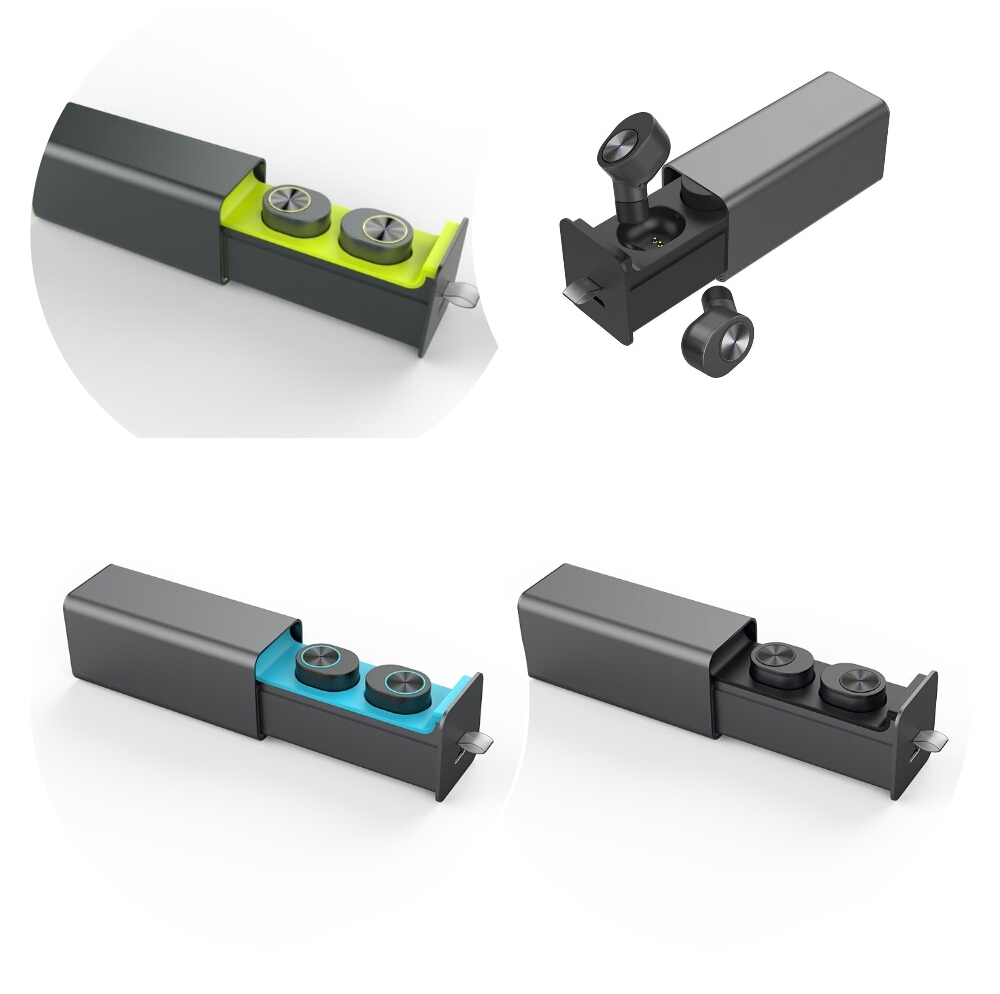
Photo as below:
Bluetooth Earbuds Bluetooth Earbuds,Wireless Earbuds,Cordless Earbuds,Wireless Bluetooth Headset Shenzhen Greater Industry Co., Ltd. , https://www.szgreater.net
![]()
![]()


