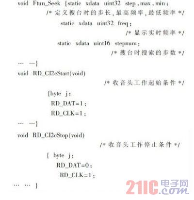
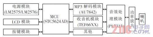
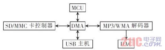
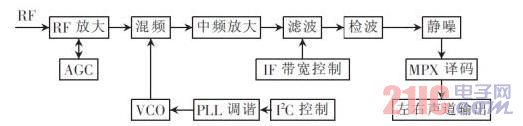
With the rapid development of automotive electronics technology, the automotive audio field is undergoing an unprecedented technological change. Users have put forward the requirements for diversified functions and user-friendly requirements for car audio, including the following three aspects: (1) Better Radio reception and easier digital tuner operation; (2) support for a variety of external storage devices, such as support for large-capacity U-disks and SD cards; (3) provide richer audio processing, such as high-pitched, heavy bass , such as the adjustment of loudness, balance, etc., as well as providing popular, rock, jazz, classical and other sound effects. Based on these needs, a digital car audio system was designed. This article refers to the address: http:// 1 I2C protocol The I2C bus acts as a synchronous serial data output bus and consists of a serial data line (SDA) and a serial clock line (SCL). It is a true multi-master bus. If multiple hosts simultaneously initiate data transfer, data corruption can be prevented by collision detection and arbitration. Each device connected to the bus can be addressed with a unique address and a simple host/slave relationship software that is always present. The host can act as a host transmitter or host receiver. 2 hardware circuit 2.1 Circuit design According to the characteristics of the car audio system, the STC12C5624AD series MCU is designed and designed. It is a 51-enhanced MCU introduced by Hongjing, featuring low power consumption and fast calculation speed. When the sound system is turned off, the MCU enters the low-power sleep state, and the MCU cuts off the power supply of all peripheral modules; when the system needs to work, the MCU wakes up through external interrupts, thus minimizing power consumption. The audio system circuit diagram is shown in Figure 1. Figure 1 Audio system module circuit diagram 2.2 Peripheral hardware modules The system takes the STC12C5624AD microcontroller as the core and controls the operation of other modules through the I2C bus. The block diagram of the hardware module is shown in Figure 2. Figure 2 Car audio system hardware module block diagram 2.2.1 Power Module The power module uses National Semiconductor's current-output step-down switching type integrated regulator circuits, the LM2576 and LM2575, which contain a fixed-frequency oscillator (52 kHz) and a reference regulator (1.23 V) with a complete protection circuit. (current limit and thermal shutdown circuit). The integrated voltage regulator circuit introduces closed-loop control, which can form a high-efficiency voltage regulator circuit with only a few peripheral components, and the output terminal voltage is stable and the ripple is small. The input voltage range is 10 V~40 V. The wide input voltage range enables the system to adapt to 12 V/24 V power supply systems, and it also solves the problem of output voltage change when the car works under different working conditions. . 2.2.2 MP3 Decoding Module The MP3 decoding module uses the AU7842, which integrates a microcontroller, MP3/WMA decoder, USB host controller, SD/MMC card controller, 16-bit audio decoder and an infrared decoder, as shown in Figure 3. Figure 3 MP3/WMV decoding module circuit The AU7842 chip decodes music files (MP3 and WMA) stored as digital signals into analog signals that can be played back. After booting, the MCU loops to detect the action of the circuit around the decoder chip. When it is detected that there is a storage device access on the periphery of the chip, the MCU control chip directly accesses the contents of the (DMA) memory, reads the data and sends it to the MP3/WMA decoder, and the decoded digital signal is converted by a digital-to-analog converter (DAC). The analog signal, analog audio amplification and low-pass filtering, you can get the music you hear. 2.2.3 Radio module The radio chip uses a low-IF tuner TEF6606 with a PLL tuning system designed by NXP Semiconductors for the car radio mainframe. In addition to the basic features, the TEF6606 also provides good weak signal processing and a dynamic bandwidth control. The working principle of TEF6606 is shown in Figure 4. The local oscillator signal is generated by the PLL tuning system. The frequency division coefficient of the programmable frequency divider is tuned through the I2C bus to change the local oscillator frequency of the voltage controlled oscillator (VCO). In order to achieve the purpose of digital tuning [4]. The schematic diagram of the radio system is shown in Figure 4. Figure 4 schematic diagram of the radio system The TEF6606 chip has a good weak signal processing function, which improves the radio performance of the car during high-speed driving and driving between mountains. 2.2.4 Sound Processing Module The sound processing module processes the sound from the MP3 decoder chip and the radio chip. The main control chip controls the corresponding register of the audio chip through the I2C bus, which can set the volume, pitch (bass, treble), balance (left and right) and loudness (front and back); select pop, rock, jazz, classical and other sound effects; chip At the low volume, the audible compensation is achieved by raising the high frequency and low frequency sounds, and the audible effect of low distortion, low noise, and low DC level shift can be obtained. 2.2.5 Button system and display system circuit The button system uses two EC11 encoders and four push button switches to facilitate the driver's operation during driving. The LCD adopts a pen segment LCD customized according to the function of the car audio, and can display loudness including audio frequency, audio playback time, U disk status, SD card status, RPT single repeat, RDM random play, ST stereo status, LOUD, etc. MUTE mute and level indication of left and right channels. 3 system software design The overall process framework for system software is shown in Figure 5. With the aid of the software, the system can complete the power-off memory function, that is, in the manual shutdown or automatic power-down, the system can remember the system's action and various settings before power-off, and directly call it at the next power-on. The radio head circuit enables manual search and automatic search in 10 kHz steps and is capable of storing 18 frequently heard bands. Figure 5 system software flow chart The power-off memory subroutine is as follows: The radio subroutine is as follows: The master chip controls the radio head register through the I2C bus, and controls the working state of the radio head by changing the logic value of RD_DAT. By pressing the keys on the keyboard, you can control the radio head to switch between the three bands. Rotate the search button to manually search the platform in steps of 10 kHz. By controlling the automatic search button, the radio head can complete the automatic search by 10 kHz steps. The digital car audio system designed in this paper is compatible with radio and MP3 playback functions, and has made great breakthroughs in MP3 audio file storage devices. The new mass storage device (USB/SD) replaces traditional cassette storage. The system is easy to operate, and the radio and MP3 playback performance is good. In order to ensure the stable operation of the system, the experiment simulates the driving condition of the car. The system is placed in the environment of -40 ° C and +60 ° C and the four-degree space vibration test bench. The results show that the system can run for a long time and the functions are stable. . The system has been successfully applied to certain branded engineering vehicles. Robotic Vacuum Cleaner,Quiet Robotic Vacuum Cleaner,Top Robotic Vacuum Cleaners, Intelligent Robotic Vacuum Cleaner NingBo CaiNiao Intelligent Technology Co., LTD , https://www.intelligentnewbot.com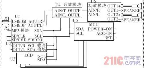
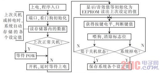
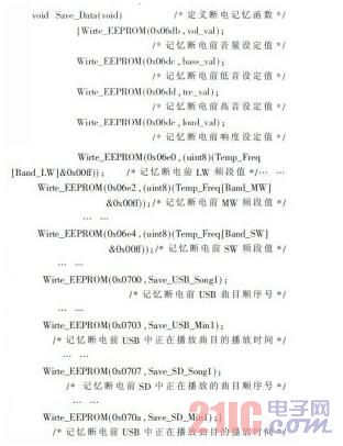
Using the power-off memory subroutine, the system will automatically save the value of the sound set by the user before the power-off, such as volume, balance, loudness, etc., and the radio before power-off, whether it is a manual shutdown or a system power failure. The band value or the time and value of the track being played in USB and SD are stored in the EEPROM through the Wirte_EEPROM function. The next time the system is turned on, the user does not have to reset it. The system can read the EEPROM value directly before the power-off. Each set value.