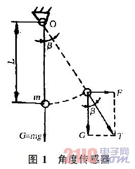
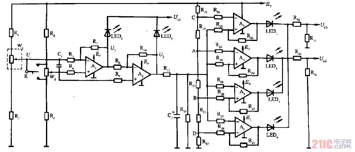
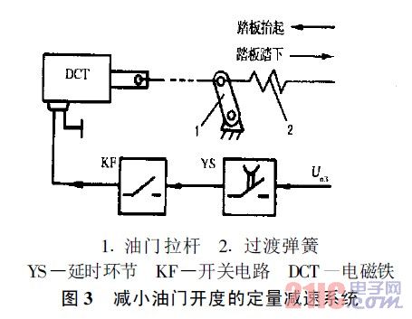
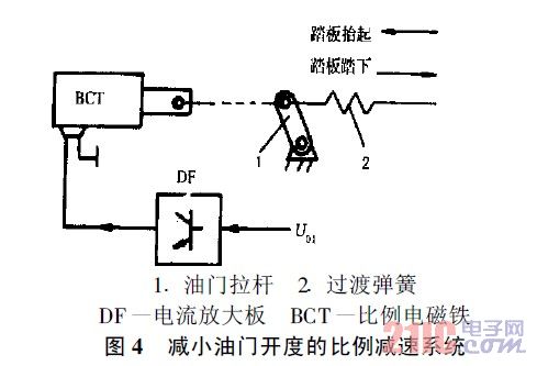
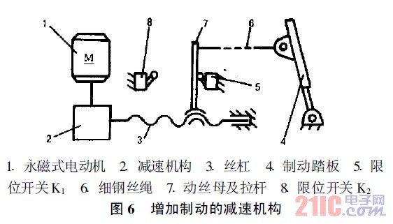
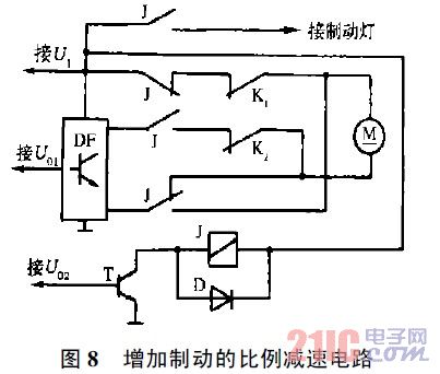
introduction This article refers to the address: http:// Overview With the development and application of electronic technology, the safety, comfort and intelligence of automobiles are getting higher and higher. The application of the vehicle lateral tilt angle sensor is an effective method to prevent the car from tipping over during driving, and is an important measure to improve the safety of the car, especially for cars with higher center of gravity such as off-road vehicles and double-decker buses. . The essence of the car tipping is that the outward tilting moment during driving is greater than the inward stable torque. When the center of gravity is constant, the tilting moment is determined by the tilting force (outward lateral force). According to physics knowledge, the tilting force is generated by the combined force of the sliding force F1 generated by the lateral (also called lateral) slope of the road surface and the centripetal force F2 during the turning, as follows: In the middle m - car quality G——gravity acceleration Α—the lateral angle between the road surface and the horizontal plane V——car speed R——turning radius It can be seen from the above formula 2 that in order to reduce the tilting force, it is feasible to reduce v only, and F2v2. According to Newton's third law of motion, the car produces a centrifugal force equal to the centripetal force and opposite in direction while turning, because the mass m of the car is constant. When the centripetal force cannot satisfy the increase of v2R, the tilting moment is greater than When the torque is stabilized, it will tip over. Therefore, the vehicle speed should be reduced, and the tilting moment should be reduced. The angle sensor is arranged laterally on the vehicle in the swinging direction. According to the angular displacement generated by the angle sensor, the tilting force generated by the sliding force and the centripetal force of the automobile can be obtained. The size of the car is decelerated when the angular displacement reaches a predetermined value. 1 angle sensor The angle sensor manufactured by the gravity principle is shown in Fig. 1. The mass of the oscillating portion is m, and the distance between the center of gravity and the rotating shaft is L. When the vehicle body is tilted or curved, the oscillating portion can be deflected. Let the force analysis in Fig. 1 be an ideal state without any friction. The force F is the result of the combined action of the sliding force F1 and the centripetal force F2. The force F is proportional to the tilting force, and the resulting deflection angle is also tilted. The force is proportional. The resultant force T of the gravitational force G and F is the tension of the pendulum. The swing angle = tg-1 (F/G) is independent of L. When the mass m is constant, it is only related to F and is proportional. Actually, since there is friction at the rotating shaft or the like, the longer L is, the larger the swing torque is, and the higher the precision. Angle sensors are often used as sampling elements in control systems, and their performance plays an important role in the overall system. Potentiometer angle sensors have been widely used in various control systems, but their disadvantages are the sliding wear and electrical noise of the contacts; the magneto-resistive angle sensor is a new type of purely resistive component manufactured by semiconductor technology. There is no contact. When the oscillating portion is deflected, the magnetic flux passing through the varistor changes, and the resistance value of the varistor is changed several times or more, thereby fundamentally eliminating electrical noise and improving the accuracy. Various angle sensors have a damping function, so that a short delay in response to the measured angle is beneficial to the control system. 2 angle sensor circuit 2 is a practical circuit of a lateral tilt angle sensor, mainly composed of a single-supply operational amplifier (such as LM324), which functions to process and amplify the linearly varying analog power outputted by the potentiometer W1 in the angle sensor. Output digital and analog quantities as specified. Let the potential of the horizontal point potentiometer W1 slide point Ui be (12)Ec (Ec is the regulated power supply voltage, usually 9V or 15V, the same below), R1, R2, R3, R4 are additional resistors, and make R1=R2 , R3 = R4, W2 is the potentiometer, the resistance is small. Adjust W2. When W1 is in the horizontal state, make the output potential of the op amps A1 and A2 (12)Ec. The operational amplifier A1 constitutes an inverse proportional operational amplifier, as the preamplifier of the circuit, the input voltage is Ui, the output voltage U1=-(R7R5)Ui, and R6=R5%R7; the operational amplifier A2 constitutes an inverter, Resistor R10 = R8, and should be such that R9 = R8% R10; output voltage U2 = -U1 = (R7R5) Ui. The output terminals of A1 and A2 are respectively composed of LEDs LED1, LED2 or gate output, so that the vehicle Uo1 can output an analog signal proportional to the input quantity Ui (variation with the tilt angle) regardless of whether the vehicle is tilted left or right. , ie Uo1=(R7R5)|Ui|, to control the circuit or mechanism behind. The LED can also indicate the tilt direction. When in the horizontal state, the analog output Uo1=(12)Ec: Figure 2 Side tilt angle sensor circuit diagram The op amps A3, A4, A5, and A6 form a window comparator respectively. The resistors R20, R23, R26, and R29 are positive feedback resistors with large resistance values ​​to improve the switching state of the op amp. The resistors R13~R17 are divided. Resistance, and should be R14=R15, R16=R17, the potential at the midpoint of the resistor R13 is (12)Ec, and the resistance of the voltage divider resistor should be determined according to the tilting force reflected by the change of U2, so that the op amps A3 and A5 The inverting input terminals, the non-inverting inputs of the operational amplifiers A4 and A6 obtain different switching conversion reference potentials, and the degree of left and right tilt of the reaction is uniform. When horizontal, U2=(12)Ec, the op amps A3~A6 output low level; when tilted, the potential of U2 changes, and the op amp A3~A6 outputs high level according to the specified requirements. For example, when the potentiometer W1 swings to the left, the U2 potential is raised. When the potential is higher than the A point, the operational amplifier A3 outputs a high level, and the diode LED3 displays the tilt direction. If the car continues to tilt to the left, the U2 potential continues to rise. When it is higher than the potential of point C, the operational amplifier A5 outputs a high level, and the diode LED5 shows the tilt direction and the degree is aggravated; similarly, if the potentiometer W1 swings to the right, the operation of the operational amplifiers A4 and A6 is also the same. The output signals of the two output terminals Uo2 and Uo3 reflect the inclination degree regardless of the tilt direction. It is obvious that when Uo3 has a high level signal output, Uo2 has already output a high level, and Uo3 reflects a degree of tilt greater than Uo2. K is an automatic complex mid-range twist switch. As a check switch of the circuit, when moving up and down, the diodes LED2, LED3, LED5 and LED1, LED4, and LED6 should be illuminated respectively. Capacitor C1 is a high-frequency bypass capacitor, C2 is a low-frequency filter capacitor, and a resistor R12 forms a discharge loop, forming a delay link, which is equivalent to an increase in damping in the sensor. 3 Application preliminary According to the foregoing description of the circuit of Fig. 2, there are two forms of application of the vehicle lateral tilt angle sensor. First, the digital signal Uo2 sent by the circuit drives the sound and light signal device to remind the driver to decelerate. Second, the digital signal Uo3 or the analog signal Uo1 sent by the circuit controls the actuator to automatically decelerate the vehicle, and uses the digital signal to form a quantitative deceleration system. When decelerating, the speed is slightly changed. The analog signal is used to form a proportional deceleration system. The deceleration effect is relatively smooth. There are two ways to achieve deceleration. One is to reduce the engine throttle opening and the other is to increase the braking. Described below. 3.1 Quantitative deceleration system for reducing throttle opening The digital signal from the sensor circuit controls the actuator (such as an electromagnet) to form a quantitative deceleration system that reduces the throttle opening of the engine, as shown in Figure 3. When the car is running normally, the throttle lever is controlled by the accelerator pedal, and the moving iron core in the electromagnet moves synchronously with the throttle lever; when the vehicle is tilted laterally (the combined value of speed, turning radius and road gradient, the same below) exceeds the set value The sensor circuit output terminal Uo3 sends a signal, after the delay link YS (such as time relay, Uo3 disappears, YS delay is disconnected, if the damping and circuit delay is sufficient, it can be set), the switch amplification step KF (such as Relay), so that the electromagnet DCT can work electrically, the moving iron core moves to the end position quickly, and the throttle lever is driven to make the throttle opening suddenly decrease. In this system, the starting position of the moving iron core is not fixed, the ending position can be preset, and the degree of deceleration obtained is different. Therefore, according to different models, the speed to be achieved by the engine deceleration should be reasonably set so that the deceleration is not too sudden. 3.2 Reduce the throttle opening proportional deceleration system In order to avoid the abrupt change of deceleration in the above system, a proportional deceleration system should be used, as shown in Figure 4. In the proportional deceleration system, the analog voltage signal is outputted by the sensor circuit Uo1, the current amplifying board DF is controlled, and different current values ​​are output according to the magnitude of the input signal Uo1, so that the proportional electromagnets generate different displacements and the throttle opening is reduced. In direct proportion to the increase in Uo1, the final result achieved by deceleration is determined by the degree of tilt. Let's look at the process of deceleration: the presence or disappearance of the output current of the current amplifier board is caused by the rising ramp delay tu and the falling ramp delay td. The rising ramp delay is the time required for the output current (average value) to reach a certain stable value (determined by Uo1) from zero. The falling ramp delay refers to the time when the control signal Uo1 disappears and the output current decreases from this stable value to 0. See Figure 5 for details. On the current amplifier board, the rising ramp delay and the falling ramp delay can be adjusted separately. The smoothness of the deceleration is determined by the rising ramp delay. The longer the rising ramp delay, the smaller the rising rate of the output current, and the proportional solenoid moves. The longer it takes to reach the end position (determined by the output current), the smoother the deceleration effect; vice versa. After the proportional electromagnet moves to a certain end position, the smooth transition of deceleration is completed. After a period of time, the tilting moment is less than the set value or disappears, causing Uo1 to decrease or disappear. If Uo1 is reduced, the output current drops by the slope determined by td until it is zero. Assuming Uo1 suddenly disappears, the output current is 0 after the delay of td, thus achieving the smoothness of re-acceleration after deceleration. For the rising ramp delay and the falling ramp delay, it should also be determined according to different vehicle models and system parameters. The output current of the current amplifier board is usually obtained by pulse width modulation (PMW) technology. The input signal Uo1 determines the duty cycle of the output current waveform and changes the average value of the current. This DC current contains a certain component of the flutter component. It can overcome the hysteresis of the proportional electromagnet and improve the position control accuracy. 3.3 Reduce the connection between the throttle opening deceleration system and the original vehicle throttle mechanism It can be seen from FIG. 3 and FIG. 4 that the displacement generated by the actuator of the deceleration system is opposite to the direction of the displacement generated by the original accelerator pedal. When the actuator reduces the throttle opening, the accelerator pedal is likely to be lifted. And to overcome the resistance of the original car throttle mechanism, if the driver's foot is on the pedal, the actuator needs to generate a large amount of force to complete the action, and at the same time, the strength and rigidity of the mechanical parts in the transmission mechanism must also be increased, so that The deceleration system is not perfect. To solve this problem, a transition spring is added between the accelerator pedal and the throttle lever, as shown in Figures 3 and 4. In fact, the force of the accelerator pedal to the throttle lever is small, and the return spring of the accelerator pedal does not directly act on the throttle lever. Therefore, the throttle pedal is directly driven by the original accelerator pedal to increase the transition spring with a moderate rigidity (tension spring) ) The throttle lever is driven, and the normal operation does not affect the throttle pedal control of the throttle lever. When the deceleration actuator is actuated, the throttle opening is reduced and the transition spring is elongated, assuming that the driver's foot is not raised, and There won't be too much pedaling up or feeling. If the position of the accelerator pedal remains unchanged, the tilting torque does not work after the deceleration phase is over, the sensor circuit stops the signal output, the deceleration actuator stops working, the transition spring is retracted, and the throttle lever is returned to the original position, which can be automated. Acceleration, the same acceleration as the deceleration is obtained in the quantitative deceleration system, and the acceleration rate corresponding to the falling ramp delay can be obtained in the proportional deceleration system to achieve smooth acceleration. 3.4 Increase the braking speed reduction mechanism The service brakes of various automobiles are all completed by the brake pedal. Therefore, the action actuator of the deceleration method for increasing the brake should directly act on the brake pedal, and the action direction of the actuator and the stepping direction of the brake pedal. It is consistent that the connection of the actuator to the brake pedal can be achieved by mechanical construction. According to the force required to step on the brake pedal, a permanent magnet DC micromotor is used as the actuator, as shown in Fig. 6. After the speed of the motor output is driven by the speed reduction mechanism, the lead screw is rotated to linearly move the moving wire on the lead screw, and then the pull rod on the moving wire is driven by a thin steel wire rope to drive the brake pedal. When the motor is not rotated, the pull rod is limited. The position switch K1 is pressed open and the brake pedal is working normally. 3.5 Two kinds of control circuits for increasing braking In the same way, the deceleration of increasing the braking can adopt two kinds of control modes, namely, a quantitative deceleration system for increasing the braking and a proportional deceleration system for increasing the braking, and their control circuits are respectively shown in FIG. 7 and FIG. 8, and the actuators are all in FIG. Electric motor. The difference is: in the quantitative deceleration circuit, the motor is directly connected to the power supply and rotates; in the proportional deceleration circuit, the motor is driven by the current amplifying board, and the pulse width modulation method is adopted to make the current amplifying board be inclined by the size of the car. During the time, the maximum output current is reached, and the motor gradually accelerates to the corresponding maximum speed, and the braking effect obtained is relatively smooth. The specific process is described as follows. When the lever is in the position shown in Fig. 6, the limit switch K1 is pressed open (the state of K1 is opposite to the state in Figs. 7 and 8), so that the motor is in a standby state. When the output terminal Uo3 in Fig. 2 has a high level signal output, the transistor T in Fig. 7 is turned on, the relay J is energized, and the contact is switched, so that the motor starts to receive the positive and negative power supply via the limit switch K2. Rotate to make the lever leave the limit switch K1, drive the brake pedal down, and generate braking. After a period of time, Uo3 has no high level output, relay J returns, so that the motor gets up and down through the limit switch K1. The power supply starts to reverse (in a short period of time, the motor is in reverse braking state, and the small-capacity DC motor will not be affected in use. It can also increase the delay and make the motor reverse. slightly). When the lever returns to the end position shown in Figure 6, K1 is opened and the motor is stopped to prepare for the next action. In Fig. 8, the base of the transistor T is connected to the output terminal Uo2 in Fig. 2. When the Uo2 outputs a high level, the tilting force is less than Uo3. When the Uo2 output is high, the transistor T is turned on, and the relay J is powered. At the same time, the analog input of the Uo1 output is input to the current amplifying board DF, so that the motor obtains the pulsating DC power supply (average value) under the positive and negative negative limit switch K2, and starts to accelerate the rotation, and the limit switch K1 is The off state is turned to the closed state (shown in Figure 6). The maximum speed reached by the acceleration is determined by the size of Uo1 at that time, and the acceleration rotation time is determined by the rising ramp delay tu of the current amplifier board (ignoring the starting inertia time of the motor) For smooth braking. As the brake is generated, Uo1 drops, and the braking force is reduced until the high level signal of Uo2 disappears, the tilting force is less than the set value, and the relay returns, so that the motor receives the power supply up and down via the limit switch K1. And quickly reversed. When the lever returns to the end position shown in Figure 6, K1 is opened and the motor is stopped to prepare for the next action. The limit switch K2 in Fig. 6, Fig. 7 and Fig. 8 is a brake protection switch to prevent circuit malfunction (such as component short circuit, grounding, etc.), so that the motor is always rotated, and the brake is endlessly increased when the lever is made When K2 is disconnected, the motor will lose power and stop. During the normal braking deceleration process, K2 disconnection will not occur. It is assumed that K2 has been disconnected. When the deceleration is over, relay J will return and the motor will be quickly. Return to the standby position to disconnect K1. In Figures 7 and 8, D is the freewheeling diode of relay J. When the relay J contact is closed, the brake light is turned on and a brake signal is issued. 3.6 Application of two deceleration methods As far as the driving conditions of the car are concerned, this is usually the case: when the engine is uphill, the engine throttle is increased, the vehicle speed is decreased, and when the gradient is steep, the engine speed will reach or exceed the rated speed, and the vehicle speed will decrease; when the vehicle is downhill, the engine idles. The speed is not too low; when the road is level, sometimes it accelerates, the engine speed is high, sometimes it is coasting, and the engine is idling. In terms of reducing the speed of the vehicle and preventing the tipping, increasing the brake deceleration is a more direct method than reducing the engine throttle opening. However, when the engine speed is high (such as the slope), the engine will be blocked. By reducing the engine throttle opening, sometimes the deceleration effect (such as the slope) is not achieved. Therefore, the application of the vehicle's lateral tilt angle sensor must meet the deceleration requirements and not cause the engine to stall. Specifically reflected in the uphill deceleration. In order to solve this practical problem, an angle sensor is used to arrange the longitudinal direction of the vehicle, and the circuit thereof is as shown in FIG. When the uphill gradient reaches the specified value (such as the maximum grade), the U2 output of the op amp A2 outputs a high level, the relay J is energized, the normally closed contact is opened, and the brake deceleration circuit is cut off (Fig. 7 The power supply U1 of Fig. 8) makes it inoperable, because under such working conditions, as long as the engine reduces the rotational speed, a good deceleration effect is obtained, and the engine stall is avoided. In the remaining conditions (when the grade is less than the specified value), the relay J does not pull in, the engine throttle opening deceleration system is reduced and the brake deceleration system is added to work at the same time to ensure reliable deceleration of the vehicle. In the circuit diagram of Fig. 9, the light-emitting diode LED2 serves as an indication of the operating power supply of the deceleration system for increasing the braking. 4 Conclusion The main circuit parameters in this paper are summarized as follows: (lateral tilting moment analog quantity Uo1;) lateral tilting torque alarm digital quantity Uo2 lateral tilting torque deceleration digital quantity Uo3; + climbing degree digital quantity Uo4; , the rising ramp delay of the current amplifying board and the delay time of the falling ramp delay td angle sensor and its circuit delay. According to the car's center of gravity, track, mass, speed, turning radius, road gradient and bump vibration, the factors should be comprehensively determined to achieve a reasonable coordination relationship, and fundamentally avoid the occurrence of lateral tipping accidents during vehicle driving.
Toggle switches, also called On Off Toggle Switches, is often used as the switching device of the equipment stalls. Meanwhile, we are also offer our customers Key Switches , Metal Switches , Automotive Switches, Push Button Switches, etc.
The Electrical Toggle Switches is a manually controlled Toggle Switches similar to the dial switch. Most of this Latching Toggle Switches are widely used in on-off control of AC and DC power circuits, and are less commonly used in circuits of several kilohertz or up to 1 megahertz. Let's take a look at the following.
1. Splash-proof knob button switch
The panel is installed with a splash-proof `O` ring seal, and the knob is a ball. It is a splash-proof ball button knob switch. Its terminals are in a straight line and the bottom of the terminals is sealed with epoxy resin. Strong corrosion resistance, suitable for automotive parts
2. Vertical Mount Right Angle Toggle Switch
The vertical mounting of the terminals and the terminal pins are right-angled, so it is a vertically mounted right-angled toggle switch. Its contacts are gold-plated and highly reliable. Mostly used in anti-theft devices, alert system.
3. Bipolar single toggle switch
At the same time, the switch breaks the phase line and the N line and controls one branch. Therefore, it is a bipolar single toggle switches. The contacts are in 3PDT form and are used for multimedia speakers and stereos.
4. Standard surface mount unthreaded toggle switches
The terminal adopts the standard mounting mode. Its sleeve has no thread. It is called a standard surface mount screw-less switch. The contacts are SPDT and its electrical life is as high as 55,000. Used for medical equipment
5. Horizontally mounted right-angle toggle switch
Compared to the vertical switch, it only changes direction to horizontal, so it is horizontally mounted right-angle toggle switch. The contacts are double-pole double-throw and the bottom of the terminal is Epoxy Seal. Mostly used for computer peripherals.
Toggle Switches Toggle Switches,On Off Toggle Switches,Micro Toggle Switches,Electrical Toggle Switches,Toggle Switch Function YESWITCH ELECTRONICS CO., LTD. , https://www.yeswitches.com