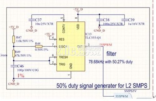
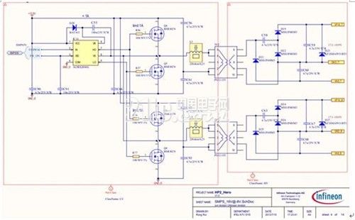
The electric vehicle inverter is used to control the main motor of the automobile to provide power for the operation of the automobile. The IGBT power module is the core power device of the electric vehicle inverter, and the driving circuit is the key circuit for exerting the performance of the IGBT. The design of the drive circuit and the drive circuit of the industrial general-purpose inverter and the wind energy solar inverter have more severe technical requirements, and the power supply circuit is limited by the small space size and high working temperature, and faces many challenges. This paper designs a drive power supply and proves its availability through actual testing. This article refers to the address: http:// Common drive power supplies are designed with flyback circuits and transformers with multiple primary and secondary sides. Since the flyback power supply provides the inherent characteristics of the energy output to the load during the off period of the switch, its current output characteristics and transient control characteristics are relatively poor. In the space layout of IGBT modules of the order of 100 kW, the design of a single transformer to produce 4 to 6 isolated positive and negative power supplies has many disadvantages: the power supply is too concentrated, the creepage distance and the clearance are difficult to guarantee, and the power supply distance of the board is high. Too long and so on. This design uses common non-dedicated chips for circuit design. The SEPIC circuit in the front stage realizes closed loop, and the isolation of the latter half-bridge circuit effectively solves the above problems. The circuit has been successfully applied to the design of international leading new energy vehicle inverters. Applications show that the design has good flexibility, high reliability and transient response. 1 Analysis of the requirements of electric vehicle inverter drive power supply The electric vehicle inverter drive power supply is generally 6 isolated +15V/-5V power supplies. The power, electrical isolation, peak current capability, operating temperature, etc. of the power supply have strict requirements. The specific calculation of the power supply index is carried out with Infineon's automotive-grade IGBT module FS800R07A2E3_B31. The module supports inverter system design up to 150kW. 1.1 Drive power calculation The input power of the drive power is calculated as: P=f_sw×Q_g×△V_g/η(1) The f_sw switching frequency is 10 kHz, Q_g is 8.6 nC according to the data sheet, and ΔV_g is 23V for the gate driving voltage. Considering that the power is small, the efficiency is 85%. Also note that the 8.6nC in the data sheet is calculated according to the voltage +/-15V, which needs to be considered for conversion, and the final calculation result is 1.8W. Consider the design margin of 1.1 times, recorded as 2W. 1.2 Drive current calculation The average drive current is calculated as: I_av=f_sw×Q_g(2) The average current can be calculated to be 86 mA. The peak current calculation formula is: I_peak=△V_g/(R_gext+R_gint)(3) R_gext is the external sector pole resistance, according to the data sheet to open the 1.8 Euro off 0.75 Euro. R_gint is the internal gate resistance, which is 0.5 ohm according to the data sheet, and the peak current is 10A, and the peak current is 18.4A. In actual use, the turn-on and turn-off resistors require a compromise between switching speed and short-circuit protection. A good design value is in the range of 2.2 to 5.1 ohms, so the actual switching peak current is in the range of 4 to 10A. 2 drive power circuit design 2.1 Power Topology Design The input of this power supply is the conventional 12V power supply of the new energy passenger car. The power supply usually has a fluctuation range of 8~16V, and the output of the driving power supply needs to be relatively stable. It is necessary to design multiple sets of isolated power supplies with wide voltage input and constant voltage output. This design divides the power supply into two levels: the front-stage power supply realizes the wide-voltage input and the constant-voltage output function, and the latter stage realizes the isolation function. The structure is shown in Figure 1. Figure 1: Schematic diagram of the power supply topology The benefits of this structure are: First, the pre-stage power supply does not need to solve the isolation problem, and can adopt the conventional SEPIC or buck-boost non-isolated topology, and the output of the pre-stage power supply is a low-voltage constant voltage without isolation, and it is not necessary to consider the creepage between the groups of power sources in the place and route. Distance and clearance problems. Therefore, the front stage of the part can be implemented independently as a low-voltage weak current circuit without occupying the area of ​​the driving board. Second, the rear-level power supply does not need to solve the feedback problem, and adopts open-loop control to avoid the trouble of isolation signal feedback. Because the working condition of passenger car equipment is bad, the working temperature varies greatly. The traditional linear optocoupler and other devices are greatly reduced in accuracy due to temperature drift, and the temperature drift compensation device is costly. This method effectively avoids this drawback. 2.2 Rear half-bridge switching power supply design The pre-stage power supply is a typical constant voltage design, and there is no need to give a design principle. This article focuses on the latter stage half-bridge circuit. The specific schematic diagram is shown in Figure 2 and Figure 3. Figure 2 shows a 50% duty cycle signal generator designed with an automotive-grade timer circuit to provide control signals to the half-bridge switching power supply. R49 can be used to adjust the switching frequency, typically between 70kHz and 300kHz. The frequency selection is mainly based on the actual space size of the board and the volt-second product of the transformer. The formula for calculating the volt-second product from the transformer is: ET=V*D/f_sw(4) V is the voltage applied to the transformer, D is the duty cycle, and f_sw is the switching frequency. This design selects a transformer with an ET value of 44Vusec, so the switching frequency is set low, 120kHz. Figure 2: 50% duty cycle signal generation circuit Figure 3 shows the half-bridge switching power supply circuit. This circuit uses an IR automotive grade half-bridge chip IRS2004S as the drive, paralleling two parallel half-bridge circuits consisting of Infineon BSR302N. A general-purpose transformer with a turns ratio of 1:1.25 is used, and a voltage of +15V is obtained by voltage doubler rectification, and a voltage of -8V is obtained by ordinary rectification. Each transformer is used to power an IGBT drive. Connecting the automotive-grade EMC magnetic beads in series on the primary side of the transformer can effectively suppress the voltage spike generated by the switch. For specific device information, see Appendix Table 1. The IGBT gate is a capacitive load. Each switch is accompanied by a higher transient current, which is the peak drive current calculated above. Therefore, a long-life capacitor with a strong ripple current capability is required. Each power supply uses 4.7uF. X7R automotive grade multilayer ceramic capacitor for transient voltage support. X7R multilayer ceramic capacitors have the advantages of small package size, low ESR, large ripple current, and reduced temperature loss. Figure 3: Schematic diagram of the half-bridge switching power supply circuit 3 test results The actual test conditions are: the final stage input constant voltage is 16.5V, the input current is 0.67A, the IGBT switching frequency is 10kHz, the signal is SVPWM, the switching power supply operating frequency is 120kHz, and the room temperature condition. According to simple calculations, the power consumption per channel is 1.84W, which is consistent with the theoretical calculation. Select the high duty cycle and low duty cycle two conditions, observe the waveform of the relevant signal, see Figure 4 and Figure 5. The orange one channel displays the low side drive input signal, the pink 2 channel displays the -8V power output waveform, the blue 3 channel displays the +15V power output waveform, and the green 4 channel displays the gate output waveform. At the time of IGBT turn-on, the charge of the power supply is quickly transferred to the gate through the gate resistor. The time is usually only 1~3us, which causes the voltage drop on the +15V power supply, but the platform voltage can be quickly recovered. Similarly, when the IGBT is turned off, the -8V power supply will also cause a voltage drop. This drop is an undesirable reaction that does not cause the IGBT to turn on or off, so it is acceptable. Comparing Fig. 4 and Fig. 5, it can also be found that the duty ratio does not affect the amplitude and duration of the voltage drop because the gate of the IGBT is a capacitive load.
Nylon PA66 sleeve is braided from 20 mil 6-6 Nylon Polyamide monofilament. Heavy duty and flexible, this sleeving is extremely versatile in any industrial application that calls for abrasion protection without any sacrifice in flexibility or durability.
Color: black, transparent
data : single wire, double wire, three wire, wire braid
Braided Expandable Cable Sleeve,Nylon Sleeve For Cable,Cable Nylon Management Sleeve,Nylon Expandable Braided Cable Sleeve Shenzhen Huiyunhai Tech.Co.,Ltd , https://www.hyhbraidedsleeve.com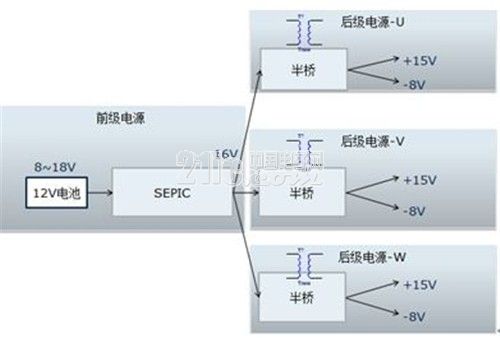
Nylon PA66 sleeveoutperforms all competitive round monofilament sleeving in standardized abrasion tests. SD is also more economical and easy to use, cutting cleanly with a hot knife, and expanding up to 50% for easy installation over plugs and connectors.
Size: 1MM--100MM