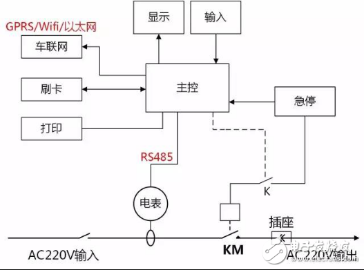
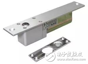
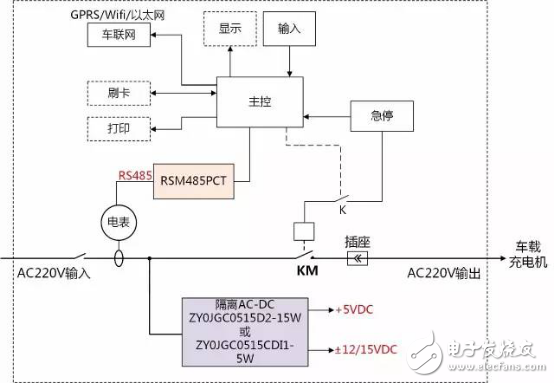
Compared with the DC pile, the AC pile has fewer power modules, and the charging power is much smaller. The electromagnetic environment is relatively friendly, but it cannot be underestimated. At the same time, for cost-effective considerations, many solutions are not suitable. From the perspective of power supply of the charging control board and RS485 isolated communication, some suitable applications are described. First, the main communication method of the exchange pile Because there is no charger on the AC pile, the charging is done by the car charger. Therefore, the CAN port is generally not required to communicate with the BMS. The main communication is RS485 and Wifi/GPRS/Ethernet, as shown: 1. RS485: The communication between the energy meter and the control unit is generally connected through RS-485, and the power consumption statistics and consumption are completed. 2, Wifi, GPRS, industrial Ethernet, etc.: mainly with the network, charging APP and other interconnections, to achieve remote monitoring, control and so on. Figure 2 Internal communication of the AC pile The RS485 communication distance inside the AC pile is very short, and most of them are one-to-one communication between the control board and the meter. The general transceiver can meet the baud rate and the number of nodes. More attention is needed to prevent interference and stability. And the cost of the overall program. Second, the low voltage system power supply inside the AC pile The low-voltage system inside the AC pile is powered by a 220VAC power grid. The required low-voltage power is generally +5VDC, and ±12VDC or ±15VDC, of ​​which 5V supplies power to the main control and display, and ±12V/±15V to the analog circuit and charge detection. Power supply such as electric plug lock. The best way to provide these DCs is with a single power supply, that is, one AC-DC provides +5V and ±12V/±15VDC multiple outputs. The more troublesome is to supply power to the electrical plug, as shown in Figure 3. The working voltage of the electric mortise lock is generally +12/+15 VDC, which basically consumes no electricity at all times. At the moment of operation, the current can reach 2A. For multi-channel power supply, ±12V/±15V is generally the auxiliary circuit of the power supply. The ability to provide transient high current is weak, and the voltage will drop rapidly at the moment of operation, which may cause the electric lock to be effectively closed/opened. Let other circuits sharing ±12V/±15VDC be affected. Figure 3 Schematic diagram of electric plug lock Third, the application scheme of power supply and RS485 isolation on the AC pile The block diagram of the scheme is shown in Figure 4: Figure 4 Power and RS485 isolation applications 1. For the power supply on the AC pile, ZLG's ZY0JGC05xx series is highly integrated, and the single input provides one positive and one positive and negative output. The product is optimized for the application of the instantaneous high current of the electric plug lock, and the electric lock is opened and closed. The power supply of the positive and negative outputs is not affected at all times, and the stability of the power supply is ensured. 2. For the RS485 isolation of the meter, the RSM485PCT product with power supply isolation output, isolation voltage support 3500VDC, industrial grade -40~85 °C wide temperature operation, effectively suppress the bus common mode noise, etc., to ensure the communication between the energy meter and the control unit Reliability. Fourth, summary Starting from the characteristics of the AC pile, a brief analysis of the internal low-voltage system power supply and RS485 communication applications, from the perspective of product reliability and cost, recommend multi-channel AC-DC and isolated RS485 module solutions.
Standard Recovery Stud Diode are mainly used for rectifying and switching
It has positive pressure reduction (0.4v -- 1.0v), short reverse recovery time (2-10ns nanosecond), large reverse leakage current, low pressure resistance, generally lower than 150V, and is used in low voltage situations.
Diodes are electronic devices that have two electrodes that allow only a single current to flow in a single direction.Varicap bond (bond) is an electronic adjustable capacitor.Most diodes have a current orientation that we call reading "rectifier".The most common function of a diode is to allow only the current to pass in one direction (called forward bias) and to block in the opposite direction (called reverse bias).
Standard Recovery Stud Diode Standard Recovery Stud Diode,Standard Recovery Diode,400V Standard Recovery Diode,Stud Diode YANGZHOU POSITIONING TECH CO., LTD. , https://www.yzpst.com